Were these codes present prior to replacement of the trans?
Are they the exact codes? Even after swapping out the valve body?
Seems we have only the other options left, a wiring or PCM fault.
I have the diagnostic procedures here, go through them and see what you come up with.
TEST A: SHIFT SOLENOID ELECTRICAL CIRCUIT
1. Electronic Diagnostics With ignition off and transmission in "P" position, ensure transmission wiring harness and harness connector is in good condition. Repair as necessary. Connect scan tester DLC. Turn ignition on. Select the following modes in order: Diagnostic Data Link, PCM, Active Command Modes, Output State Control (OSC), Trans-Bench Mode. If vehicle enters Trans-Bench Mode, go to next step. If vehicle will not enter Trans-Bench Mode, diagnose fault in PCM or scan tool. See appropriate TESTS W/CODES article in ENGINE PERFORMANCE section.
2. Wiggle Test While in Trans-Bench Mode, select Parameter Identification (PID) Access Mode. Select a shift solenoid to monitor. Select ON then SEND to operate selected solenoid. While monitoring solenoid output state, wiggle transmission wiring harness and connector. Repeat for each shift solenoid and TCC solenoid. If solenoid output state does not change, go to next step. If solenoid output state changes, repair open or short in wiring harness and/or connector.
3. Solenoid Functional Test Using scan tool, turn each solenoid on and off. If each solenoid can be heard changing state, go to next step. If any solenoid could not be heard changing state, go to step 5).
4. Output State Control (OSC) Mode Perform OSC TRANSMISSION DRIVE
MODE. See OSC TRANSMISSION DRIVE MODE. Perform TCC DRIVE MODE. See OSC TRANSMISSION MODE. If transmission does not shift properly or TCC does not engage properly, go to next step. If transmission shifts properly and TCC engages properly, clear all DTCs. Test drive vehicle and verify no problems exist. If any problems still exist, diagnose by symptom.
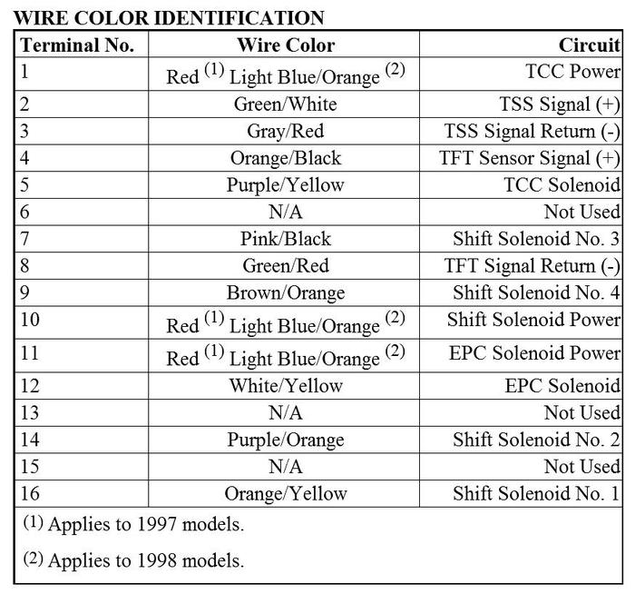
5. Power Supply Remove transmission fluid pan. Check solenoid wiring harness and connectors for damage. Turn ignition on. Using DVOM, measure voltage between transmission solenoid connector terminal No. 1 and ground. If battery voltage exists, go to next step. If battery voltage does not exist, check for open or short in wiring harness and connectors.
6. Electrical Signal Test Using DVOM, connect positive lead to transmission wiring harness connector terminal No. 1. Connect DVOM negative lead to each shift solenoid and TCC connector terminal. See TRANSMISSION CONNECTOR TERMINAL IDENTIFICATION table. With scan tool in Trans-Bench Mode, turn each solenoid on and off. Monitor DVOM and listen for solenoid state to change. If voltage and solenoid state changes, go to next step. If voltage or solenoid state does not change, check for open or short in wiring harness or connectors between PCM and transmission.
7. Check Solenoid Resistance Disconnect each solenoid (SS1, SS2, SS3, SS4, TCC) wire connector. Measure resistance between solenoid terminals. Resistance should be 22-48 ohms for shift solenoids No. 1-4 and 9-16 ohms for TCC solenoid. If resistance is as specified, go to next step. If resistance is not as specified, replace appropriate solenoid.
8. Check Solenoid For Short To Ground Disconnect each solenoid (SS1, SS2, SS3, SS4, TCC) wire connector. Using DVOM, measure resistance between solenoid terminals. Infinite resistance should exist. If resistance is not as specified, replace solenoid. If resistance is as specified, diagnose problem by symptom.
P1747
TEST E: EPC SOLENOID [ PINPOINT TESTS: 1998 MODELS ]
0. Electronic Diagnostics - Turn ignition off. Ensure transmission harness connector is in acceptable condition. Repair as necessary. Install NGS scan tool. Turn ignition on. Follow on screen and select TRANS-BENCH mode in OUTPUT STATE CONTROL (OSC) mode. If vehicle enters TRANS-BENCH mode, go to next step. If vehicle will not enter TRANS-BENCH mode, see appropriate TESTS W/CODES article in ENGINE PERFORMANCE section.
0. Check Solenoid Operation - Install a 300 psi pressure gauge to EPC pressure port. Start engine. While monitoring pressure gauge, enter a value between 0-90 in increments of 15 then press SEND. Select a different value between 0-90 and observe pressure gauge. EPC pressure should match value entered in psi (example: value 30 entered, gauge should read 30 psi). If EPC pressure is not as specified, go to next step. If EPC pressure is as specified, erase all trouble codes. See CLEARING CODES. Repeat QUICK TEST.
0. Check VPWR Signal Circuit - Turn ignition off. Drain transmission fluid and remove pan. Inspect internal wiring harness for damage. Repair as necessary. Turn ignition on. Using DVOM, measure voltage between internal wiring harness terminal No. 4 and ground. If battery voltage exists, go to next step. If battery voltage does not exist, repair open or short in circuit. Erase all trouble codes.
0. Check Electrical Signal - Using DVOM, measure voltage between internal wiring harness terminals No. 4 and No. 6. See Fig 2. Using NGS scan tool, turn solenoids on and off. Ensure solenoids activate. While monitoring DVOM, select a value between 0-90 in increments of 15 and press SEND. Select a different value between 0-90 and press SEND. Enter "XXX" then press SEND to turn any activated solenoids off. If voltage and solenoid state changes, go to next step. If voltage or solenoid state does not change, check for open or short in wiring harness between PCM and EPC solenoid.
0. Check Solenoid Resistance - Disconnect transmission harness connector. Using DVOM, measure resistance between EPC solenoid terminals. Resistance should be 2.48-5.66 ohms. If resistance is as specified, go to next step. If resistance is not as specified, replace EPC solenoid. Erase all trouble codes. Repeat QUICK TEST.
0. Check For Short To Ground - Using DVOM, measure continuity between each EPC solenoid terminal and ground. If continuity exists, replace EPC solenoid. If continuity does not exist, EPC solenoid circuit is okay. Diagnose by symptom.
Image (Click to make bigger)
Sunday, June 3rd, 2012 AT 8:50 AM


