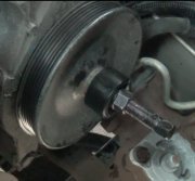
The steering box needs to be adjusted, Best left to an expert, if done wrong the pitman shaft can be cut in half causing steering loss! But here's how.
PITMAN SHAFT OVER-CENTER TURNING TORQUE OVERHAUL
NOTE:
Adjust worm bearing preload before performing this procedure. See
WORM BEARING PRELOAD. This procedure adjusts clearance
between rack piston and pitman shaft sector teeth.
Remove steering gear. See STEERING GEAR under REMOVAL & INSTALLATION.
Rotate stub shaft in both directions to drain fluid from steering gear. Loosen pitman shaft
adjuster lock nut. See Fig. 1. Rotate pitman shaft adjuster screw counterclockwise until fully
extended, and then turn clockwise one full turn.
1.
Turn stub shaft from stop to stop, counting number of turns between stops. Beginning at either
stop, turn shaft away from stop 1/2 the number of turns counted. This centers the gear. With
gear centered, flat on stub shaft should face upward, parallel to side cover, and master spline on
pitman shaft should align with adjuster screw.
2.
Using an INCH-lb. Torque wrench with handle pointing upward, rotate stub shaft 45 degrees to
each side of center to measure worm bearing preload torque. See Fig. 9. Record highest turning
torque measured on or near center.
3.
If turning torque measured is not 6-15 INCH lbs. (.7-1.7 N.M), turn pitman shaft adjuster screw
clockwise until torque is as specified, and then tighten screw an additional 6-10 INCH lbs. (.7-
1.1 N.M). While preventing adjuster screw from turning, tighten lock nut.
WORM BEARING PRELOAD OVERHAUL
1. Remove steering gear. See STEERING GEAR under REMOVAL & INSTALLATION.
Rotate stub shaft in both directions to drain fluid from steering gear. Using punch, remove
adjuster plug lock nut from adjuster plug near stub shaft. See Fig. 1.
2. Using Spanner Wrench (J-7624), tighten adjuster plug until firmly seated in housing. See Fig.
8. This requires 22 ft. Lbs. (30 N.M) of torque. Mark gear housing at a place opposite one hole
in adjuster plug. Measure back (counterclockwise) 1/2" (13 mm) from first mark, and then
make another mark on housing.
3. Turn adjuster plug counterclockwise until hole in adjuster plug is aligned with second mark on
housing. Hold adjuster plug to maintain alignment with index mark. Tighten adjuster plug lock
nut securely.
NOTE:
This procedure adjusts amount of compression force exerted by the
worm shaft on worm shaft conical bearing.
Images (Click to make bigger)
Sunday, February 20th, 2011 AT 6:41 AM


