Welcome back:
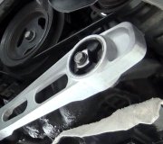
Yes, there are. I didn't know what engine you had, so rather than guessing, I didn't include these. The attached pictures correlate with these directions.
_______________________________
FRONT
Front Engine Mount Removal and Installation Procedure
Note: The front engine support insulators are located on each side of the cylinder block. These procedures apply to either a RH or LH cylinder block (6010) installation. When self-locking (adhesive on threads) mounting bolts and nuts are removed, they must be replaced with new self-locking bolts and nuts. Prior to installing the new self-locking mounting bolts, the hardened residual bolt adhesive must be removed from the engine block bosses with an M10 x 1.5 bottoming tap.
Front Engine Support Insulators
See Picture 1
1. Disconnect battery ground cable.
2. Remove engine cover assembly.
3. Remove air cleaner outlet tube to the engine air cleaner.
4. Install Rotunda Engine Lifting Bracket set.
5. Install Three Bar Engine Support D88L-6000-A or equivalent to engine lifting brackets and support engine.
Caution: Raise engine carefully so as not to damage lines and hoses at rear of engine.
6. Raise vehicle on hoist.
7. Remove front engine support insulator through bolts.
8. Remove any accessory and oil cooler line retaining clips from front engine support insulators.
9. Remove front anti-lock brake wire harness from body and front sub-frame retainers.
10. Remove steering coupling pinch bolt.
11. Separate steering coupling from lower steering column shaft (3B676).
12. Support LH front suspension lower arm (3079) and RH front suspension lower arm and remove front strut through bolt. Separate struts front front suspension lower arms.
13. Slowly lower front suspension lower arms until hanging freely.
14. Support front sub-frame with jackstands.
15. Remove eight front sub-frame retaining bolts.
16. Slowly lower front sub-frame to gain access to front engine support insulators.
17. Remove bolts retaining front engine support insulators.
18. To install, reverse removal procedures. Align sub-frame as outlined. Tighten front engine support insulators to engine bolts and studs to 53 - 71 Nm ( 40 - 53 lb ft ). Tighten front sub-frame bolts to 34 46 Nm ( 89 - 118 lb ft ). Tighten front tension strut to front suspension lower arm bolts to 120 - 160 Nm ( 89 - 118 lb ft ). Tighten steering coupling pinch bolt to 28 - 40 Nm ( 21 - 30 lb ft ). Tighten front engine support insulator through bolts to 47 - 63 Nm ( 35 - 46 lb ft ).
19. Check front end alignment. Adjust if necessary.
__________________________________________
REAR
Rear Engine Mount Removal and Installation Procedure
Picture 2
Picture 3
Removal
1. Raise vehicle on hoist.
Note: Keep automatic transmission weight on the mount during nut removal.
2. Support automatic transmission with a jack and wood block. Remove the rear nut retaining the rear engine support insulator (6068) to the rear engine support (6A023).
3. Remove two bolts retaining the rear engine support to the transmission support members (7K065). Remove rear engine support.
4. Remove two bolts retaining rear engine support insulator to the rear engine support mounting bracket (6A026). Remove rear engine support insulator.
Installation
1. Position rear support insulator on rear engine support mounting bracket, Install two retaining bolts. Tighten to 47 - 63 Nm ( 35 - 46 lb ft ).
2. Install rear engine support to the transmission support members. Tighten retaining bolts to 47 - 63 Nm ( 35 - 46 lb ft ).
3. Lower automatic transmission. Install rear engine support insulator to the rear engine support retaining nut. Tighten to 88 - 119 Nm ( 65 - 88 lb ft ).
4. Lower vehicle.
__________________________________
Let me know if this is what you needed.
Take care,
Joe
Images (Click to make bigger)
Monday, April 1st, 2019 AT 5:18 PM


