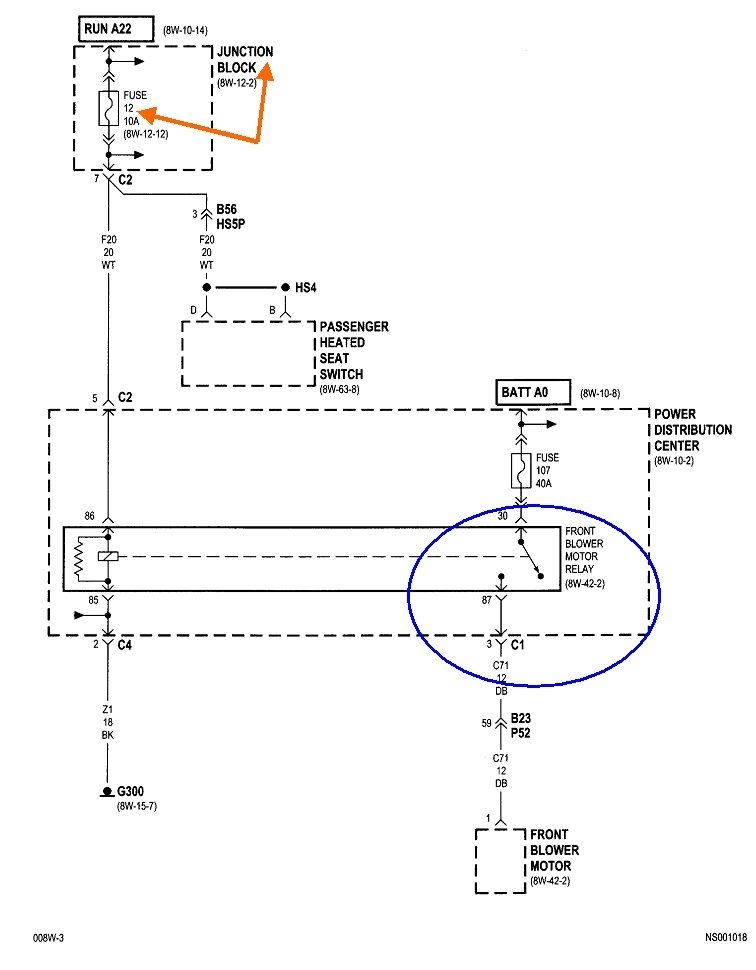
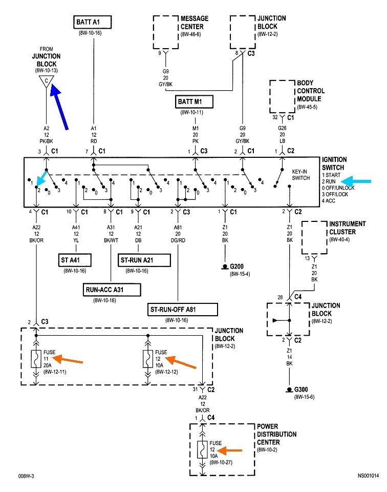
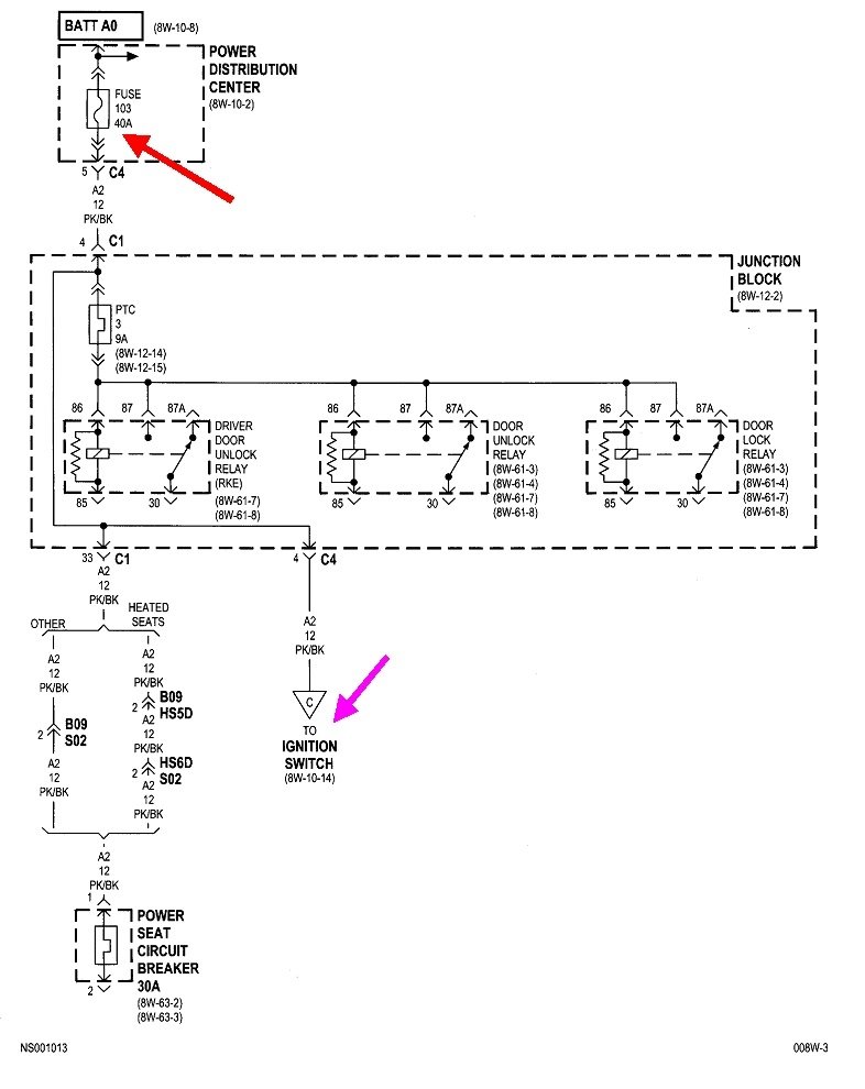
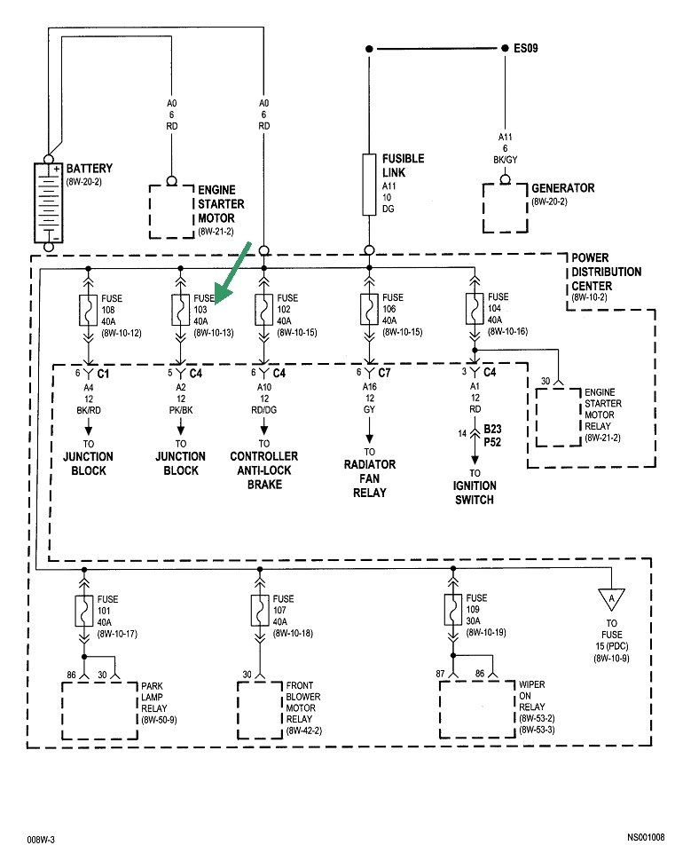
Assuming these symptoms all act up at the same time, we have to look for what they all have in common. These are the pertinent diagrams for these circuits. When you see "Power Distribution Center", that's the under-hood fuse box. The "Junction Box" is the fuse box inside the vehicle.
The first diagram shows the blower fan relay is powered through fuse 12 in the Junction Box, and that comes from circuit "Run A22" which comes from the ignition switch. Let me point out that it is fairly common to find two overheated terminals in the ignition switch connector, and those are for the section that turns the heater fan on. These fail most often for owners who are in the habit of turning the ignition switch on and off while the heater fan is set to one of the higher speeds. That causes a lot of arcing across the contacts in that part of the ignition switch, which leads to the overheated switch and terminals. In this case we have to look further back because the power locks have nothing to do with the ignition switch.
The second diagram shows circuit "Run A22". Three fuses are powered through that circuit, including the middle of the three orange arrows. That's the one we just looked at for the blower fan relay. There's actually six individual switches in the ignition switch assembly. The light blue arrow shows where that part will be when it's in the "run" position, position number 2. That circuit is powered through wire A2 12PK/BK "A" wires come from the battery. This is circuit number 2, and it's a 12-gauge pink / black wire. The dark blue arrow shows we have to work back to point "C" on the preceding diagram. That's the third one I posted.
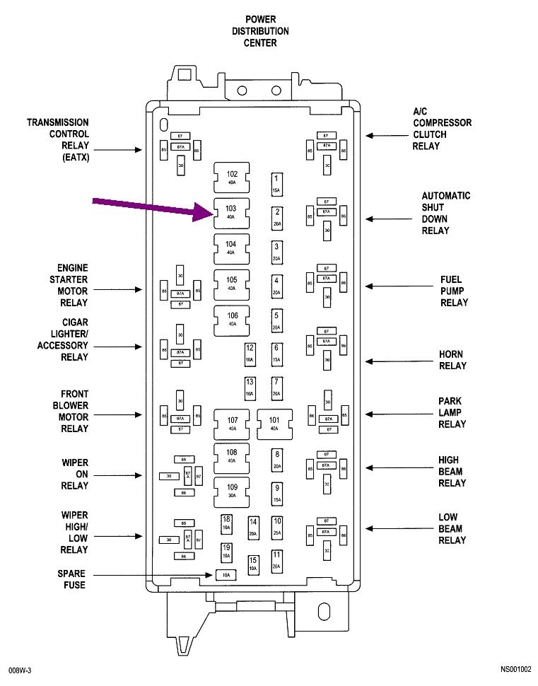
Point "C" is pointed out by the purple arrow. If you follow that back up, you'll see it comes from fuse 103, a 40-amp. That's going to be a large one physically. And guess what? That came through the Junction Block where it's also feeding the door lock relays.
The break has to be in this circuit, but the fuse is not blown because the systems in question would never work intermittently as yours are. The fourth diagram shows eight fuses, plus others not shown on this part, that are all tied together and fed from the battery. All of those other circuits do not quit, so we know everything has to be okay up to that point. While there is a place where there could be a break inside the fuse box, it is much more likely we're going to find fuse 103 has corroded terminals, or one of the wires is corroded off its terminal under that fuse's socket.
To start the diagnosis, turn the ignition switch to "run", and turn the heater fan to one of its middle speeds, then go under the hood and press on fuse 103. Wiggle it if necessary and listen for the fan to start or stop. If it does, we're in the right area. If it's running or not, and you can't make it change, we have to wait for it to go dead, then do some testing with a test light.
Here's an article about using a test light, if you need it:
https://www.2carpros.com/articles/how-to-use-a-test-light-circuit-tester
You can find a good one at Harbor Freight Tools, Walmart, or any hardware store. Some of the new ones are expensive and have lots of electronics inside. For this type of problem, those features can defeat the reason I'm having you use one instead of a voltmeter. Look for a regular, inexpensive one with a simple incandescent light bulb inside. They cost around three to five dollars.
The fifth drawing shows the PDC layout with a nifty purple arrow pointing to fuse 103.
Images (Click to make bigger)
SPONSORED LINKS
Tuesday, February 23rd, 2021 AT 10:57 PM
