Hi and thanks for using 2CarPros.com. First and foremost, you need to make sure the transmission fluid is not overfull. Additionally, if you have not had it serviced, the filter may be partially blocked causing pressure to build and then release, causing the bang.
Here are general directions for servicing the transmission:
https://www.2carpros.com/articles/how-to-service-an-automatic-transmission
If it has been serviced and you are confident that the filter is good, I would question line pressure. The transmission produces hydraulic pressure to engage gears. To check line pressure, you will need a gauge and to connect to a test port or the transmission cooling line. Most parts stores will lend you the gauge.
As far as pressure, at an idle you should have the following:
in park or neutral - 50 to 65psi
reverse - 65 to 85psi
drive 50 to 65psi
IF you determine the pressure is too high and the solenoid needs replaced, here are specific directions for your vehicle to remove the valve body (which is in the transmission under the transmission pan) from alldata. You will see wiring colors which are related to all electrical components. The pressure solenoid is listed.
Removal:
Remove the fluid pan.
Disconnect the transmission fluid temperature (TFT) sensor electrical connector.
Remove the fluid filter.
Note: It is necessary to note the location of the main control wire harness connectors so they can be connected in the same positions. Connector color letters are cast into the solenoid body.
Remove the ground wire bolt. Disconnect the electrical connectors and remove the main control wiring harness.
Solenoid SSC; Color N (Neutral/White).
Solenoid SSE; Color G (Green).
Solenoid SSD; Color L (Blue).
Solenoid EPC; Color B (Black).
Solenoid SSA; Color N (Neutral).
Solenoid SSB; Color B (Black).
Note: Note the locations of the two long bolts.
Remove the main control valve body and accumulators.
Note: Each accumulator is equipped with two springs. All four springs are different sizes.
Note: Note the size and location of the accumulator springs to aid assembly.
Note: Note the shape of each piston and the piston bore from which the piston was removed. The shape and size will very depending on application. The piston must be installed in its correct bore during assembly.
Remove the accumulator pistons and springs.
Installation:
Note: The thin longer springs are for the neutral and drive accumulator.
Note: Accumulator bore and pistons are matched by depth; some pistons may have steps. Install the pistons in the same bore as removed.
Install the accumulator pistons and springs.
Accumulator 1 and 2.
Accumulator N and D.
Caution: Make sure that the manual valve is in the manual control valve shift lever.
Note: Do not fully tighten the main control valve bolts at this stage.
Install the main control valve body.
Tighten the main control valve body retaining bolts.
Tighten the bolts in the sequence shown.
Note: It is necessary to connect the electrical connectors in the same positions as noted in disassembly. Connector color letters are cast into the solenoid body.
Install the main control valve wiring harness, connect the electrical connectors and install the ground wire bolt.
Solenoid SSC; Color N (Neutral/White).
Solenoid SSE; Color G (Green).
Solenoid SSD; Color L (Blue).
Solenoid EPC; Color B (Black).
Solenoid SSA; Color N (Neutral).
Solenoid SSB; Color B (Black).
Install the fluid filter.
Connect the TFT sensor electrical connector.
Install the fluid pan.
Fill and check the fluid level.
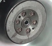
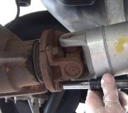
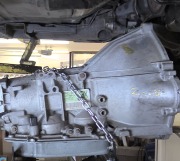
I have attached pictures relevant the the aforementioned directions.
I hope this helps.
Take care,
Joe
Images (Click to make bigger)
Monday, May 14th, 2018 AT 6:18 PM


