Hi pkruczko,
Here are the diagnostic procedures and possible causes.
DTC P0401: INSUFFICIENT EXHAUST GAS RECIRCULATION (EGR) FLOW DETECTED
Circuit Description
EGR system recirculates exhaust gas through intake system to reduce combustion temperature and NOx emissions. Amount of EGR valve opening is regulated by EGR vacuum modulator according to engine load. Vacuum source to EGR valve is controlled by EGR Vacuum Switching Valve (VSV), which is controlled by ECM. EGR valve is closed (EGR VSV is on) when engine is not warmed up, vehicle is under deceleration, under light engine load or engine is racing. DTC is set when EGR temperature sensor value does not exceed ambient air temperature by more than 86 °F (30 °C) after vehicle is operated for 3-5 minutes (50 MPH or more). Possible causes are:
"� EGR temperature sensor circuit is open.
"� Defective EGR temperature sensor.
"� EGR vacuum hose is disconnected.
"� EGR VSV circuit is open or shorted.
"� Defective EGR VSV.
"� Defective EGR vacuum modulator.
"� EGR valve is stuck closed.
"� Defective ECM.
Test Drive Confirmation
1 . Connect scan tool to Data Link Connector (DLC) No. 3. Start and warm engine to normal operating temperature with all accessories off. Operate vehicle at 43-56 MPH for 3 minutes or more. Stop vehicle and allow to idle for about 2 minutes.
2 . Operate vehicle at 43-56 MPH for 3 minutes or more. Stop vehicle and allow to idle for about 2 minutes. Turn ignition off. Start engine. Operate vehicle at 43-56 MPH for 3 minutes or more. Stop vehicle and allow to idle for about 2 minutes. Operate vehicle at 43-56 MPH for 3 minutes or more. Stop vehicle and allow to idle for about 2 minutes.
NOTE:
INCMPL is displayed on scan tool when system check is incomplete or a malfunction exists in system. If a malfunction exists, MIL will illuminate after step 2) .
3 . Using scan tool, check READINESS TESTS. If COMPL is displayed on scan tool and MIL is not illuminated, system is normal. If INCMPL is displayed and MIL is not illuminated, repeat test drive procedure.
Diagnosis & Repair (Using OBD-II Scan Tool)
1 . Disconnect EGR temperature sensor harness connector. Measure resistance between EGR temperature sensor terminals (component side). If resistance is 600 k/ohms or less, go to next step. If resistance is more than 600 k/ohms, check EGR temperature sensor. Replace EGR temperature sensor as necessary.
2 . Turn ignition on. Measure voltage between EGR temperature sensor harness connector terminals. If voltage is 4.5-5.5 volts, go to step 4. If voltage is not 4.5-5.5 volts, go to next step.
3. Access ECM behind glove box. Using DVOM, backprobe ECM harness connector. On models with California emissions, measure voltage between terminals No. 18 (Blue/Black wire) and No. 19 (Pink wire) at ECM harness connector E6. On models without California emissions, measure voltage between terminals No. 9 (Blue/Black wire) and No.
11 (Pink wire) at ECM harness connector E6.
. On all models, turn ignition on. If voltage is 4.5-5.5 volts, repair open in wiring between EGR temperature sensor and ECM. If voltage is not 4.5-5.5 volts, replace ECM.
4 . Check all EGR system vacuum hoses. If problem exists, replace vacuum hoses as necessary. If problem does not exist, go to next step.
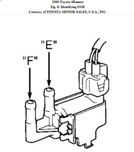
5 . Access ECM behind glove box. Ensure ignition is off. Disconnect ECM harness connector E6. Turn ignition on. On models with California emissions, connect a jumper wire between ground and terminal No. 5 (Pink/Black wire) at ECM harness connector E6. On models without California emissions, connect a jumper wire between ground and terminal No. 15 (Pink/Black wire) at ECM harness connector E6. On all models with jumper wire connected, air applied to port "E" of EGR VSV should flow from port "F".

Disconnect jumper wire. Air applied to port "E" of EGR VSV should not flow from port "F". If EGR VSV operates as specified, go to step 8. If EGR VSV does not operate as specified, go to next step.
6 . Turn ignition off. Disconnect EGR VSV harness connector. Measure resistance between EGR VSV terminals. Resistance should be 33-39 ohms at 68 °F (20 °C). Measure resistance between each terminal and body of EGR VSV. Resistance should be infinite. If resistances are not as specified, replace EGR VSV. If resistances are as specified, go to next step.
7. Apply battery voltage and ground to EGR VSV terminals. Apply air pressure to EGR VSV port "E". Air should flow from port "F". Remove battery voltage from EGR VSV terminals. Air should not flow from port "F". If EGR VSV operates as specified, repair
open in wiring between EGR VSV and ECM. If EGR VSV does not operate as specified, replace EGR VSV.
8 . Check EGR system components. If problem exists, repair as necessary. If problem does not exist, go to next step.
9 . Check EGR vacuum modulator. If problem exists, replace EGR vacuum modulator. If problem does not exist, go to next step.
10 . Check EGR valve. If problem exists, replace EGR valve. If problem does not exist, go to next step.
11. Disconnect EGR temperature sensor connector. Start engine. Ensure engine is at normal operating temperature. Run engine at 4000 RPM for 3 minutes and measure resistance between EGR temperature sensor terminals (component side). If resistance is 4300 ohms or less, replace ECM. If resistance is more than 4300 ohms, replace EGR temperature sensor.
Tuesday, February 2nd, 2010 AT 9:59 AM


