Testing the sensor of an HVAC actuator

Tiny
KDRAGGOO
  • MEMBER
  • 2012 BUICK ENCLAVE
  • 2WD
  • AUTOMATIC
  • 90,000 MILES
After the car battery died and we had to jump it, none of the 4 front actuator are working. Fuses look fine. I reset the system by removing the instrument panel HVAC fuse for 10 minutes. No improvement.

I took the driver side actuator out and took it apart. All resistors tested fine. 12v on the motor circuit turned the motor as expected. Reversing popularity reversed the motor.

The problem is I don’t know how to test the other circuit present in the actuator. It has 3 wires and appears to be some sort of sensor.

In any case, I put the actuator back in and the original problem persists.

So, any idea on how to test the internals off that sensor circuit? Any other ideas to test?

Kevin Draggoo
Thursday, December 12th, 2019 AT 9:24 PM
3 Replies

Tiny
STEVE W.
  • MECHANIC
  • 13,440 POSTS
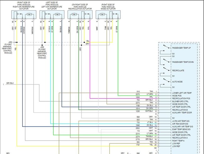
The other sensor is nothing but a potentiometer. One terminal goes to a bias voltage, the other end to ground and the last is the signal wire. However it isn't likely that all 4 actuators all failed at once. More likely is that the jump sent enough of a voltage spike through the system that the HVAC controller failed internally. For testing that you need a scan tool with bi-directional control that can read the systems inputs and then send control signals to the actuators and see what responds. Normally if it's an actuator they will either not respond at all - motor or gearing failure, or they will travel back and forth - loss of the position signal so the system just keeps moving them until it times out and sets a code.
Was this
answer
helpful?
Yes
No
Sunday, December 15th, 2019 AT 10:13 AM
Tiny
KDRAGGOO
  • MEMBER
  • 2 POSTS
Great info! Follow up question. What commands do I use to test the voltages and then test the actuators?
Was this
answer
helpful?
Yes
No
Sunday, December 15th, 2019 AT 5:29 PM
Tiny
STEVE W.
  • MECHANIC
  • 13,440 POSTS
If you have a scan tool that can control the HVAC module it will have specific tests in it to test the actuators as they are installed. Test wise you pretty much can see all the voltages testing one actuator. The Yellow wire is ground for the position sensor, the Gray wire is the 5 volt reference for it, those are shared by all the actuators up front. The motors themselves use 12 volts and polarity reversal. So if you took the one you took apart and look at the wiring the motor should be a light green and dark blue. If you connect to that and use the hot cold control you should see 12 vols that reverses polarity to drive the motor. If you don't see that then it is likely the controller itself that has went bad. Unless there is no power to the control head itself.
Was this
answer
helpful?
Yes
No
Sunday, December 15th, 2019 AT 6:04 PM

Please login or register to post a reply.

Sponsored links