Suspicion that I have assembled timing out of time?

Tiny
RQCOOK
  • MEMBER
  • 2012 JEEP PATRIOT
  • 2.4L
  • 4 CYL
  • 4WD
  • AUTOMATIC
  • 140,000 MILES
Last week - I pulled the timing cover and all - and changed the timing chain, tensioner and guides - no more. Chain had dark colored links for cam gears and crank gear marks. I considered I did a through job - chain stretch was minimal. Did not change cam gears or crank gear. . Renewed ft crank seal. Resealed with the high oil resistance ultra black, Pulled the oil pan, cleaned the rtv out of the bottom, resealed. New valve cover gasket, spark plugs and intake manifold. Replaced the water pump. 2x. 1st the af just poured through as if no gasket - even though that ultra black was used. 2nd sealed up well. I laid the ecu over to one side - and it rained. I falsely believed that the control board would have been a sealed unit with epoxy or rtv between the pins in their receptacles- and came to find out that the ecu became filled with water - where it was laying. Uncrimping and drying out - did not allow this engine to start. I ordered one from a reflasher - and it arrived in today's mail. The engine would not start immediately. Had a horde of stored codes. Cleared them. Engine started. Ran a bit - and things smoothed out. I had complications - 1 was that the brake pedal was and still is hard. I have smoke checked the intake. Put a vacuum pump on the brake booster - and have a normal assisted pedal. I put a vacumn gauge on the hose to the check valve and have 16 0 18 inch vacuum. Pushed a drill bit into the nipple for the hose going to the brake booster - with no obstruction. Drove it down the street a little ways. And back. In the assembly of the chain and gears - I had turned this engine by hand 2 full revolutions clockwise - so that the spring in the tensioner could push out all the slack it could from the chain - and then brought the engine CC back to where I had set it up - reverifying the timing marks on the chain to the cam gears and the dark color link to the crank gear. I felt pretty good with all of that. I did not expect to have any problem. The low vacuum - I can not explain - and I am headed toward pulling the valve cover again and the timing cover again and verifying the crank dot mark and the cams index marks - across from themselves in the slight arch way of the head. I have no belief that I ever would have it so lucky that the dark colored links would ever just line up - and be where I need them to be. So - What I am asking of you - is the at the point of verifying the crankshaft TDC - I know of using a skinny and putting it into #! - And rocking it around - and watching #1 intake valve open and close - but there is just a small bit of motion there at TDC that can be off by a link - I guess. So - As I understand the pointer on the timing cover - there are 3 marks on that boss. Facing it head on - TDC is supposed to be the mark on the bottom right - as per Microsoft CoPilot. - But I don't know this. The crankshaft TDC might be the first mark on the left of the pointer boss. In any event - The engine runs and went up to 4,000 rpm and seemed normal enough. Only one time out of the few minutes of run time did it seem to stumble a little bit - like a plug misfiring and then cleared up. But still low vacuum - no brake assist. The reflashed engine computer seemed to work well. But - I don;t know much of the circuits that are tied into the wiring and - I acknowledge that I had attempted to run this engine with water in the ecu case - where current could go anywhere and did go where it could go - resulting in a no start. The replacement ecu came this morning in the mail 2 days out of Ohio. Now - I had 2 fault codes related to the electric throttle body - P2122 D circuit and P3237 E circuit that never would clear by scanner delete. Removing the negative battery cable cleared those out. But there was yet another fault code that has appeared - that has not been there before doing the all of this - and that is a low voltage fault in the brake light switch. I've tried removing this fault several times - and it will not go away. I have replaced the switch with a new one - and - I did not expect it to go away - and it did not. . As I read - one of the suggestions is that the body control module has a fault. And before I do any more changing of parts - I am just chewing on what I can do - short of taking a razor blade and opening up the wiring harness wrap from the BCM to the brake light switch to look for a melted wire that may have happened when the water logged ECU was attached. Yes, I saw when I attached the last battery terminal - back when I wanted it to first run - a current path draw. I knew I was in for a ride of trouble. I just did not know how far it was going to go. In the mean time - Saturday last - I received Camber adj bolts, o/s tie rod ends and the lower left control arm - and worked to replace these items - in preparation for a FEA - to stop the inside tire wear that is happening. I am pausing to take a breath. Getting a bit tired of all that I have worked to do - but know I need to go further on down the track - to the next train station - before I can get off and be happy. I do not know if any of this you may have heard of or experienced or wish to even address. And if you don't - I can understand why. So - first I need to verify the actual position of TDC for the crankshaft - and verify the camshaft gear oblong marks facing themselves - under the valve cover. If they are off - I will need to pull the cover and set it up again - which is the only reason that I can begin to understand - the why of having low vacuum volume. The PO572 Brake Switch Code - If we lean toward a BCM - then shouldn't a similar model with the same heated seat option being coded even to a different VIN - do you have any experience that the BCM may function as needed - or - from the front side of asking this question - would need to be programmed to my wife's VIN on this Jeep. All of this - that comes from my wanting to know that I know that the whirling whine that comes out of our power train was not timing chain, tensioner or serpentine belt, tensioner bears or idler bearings. I changed all of it - at the 140,000 miles point. 5,000 miles ago - I changed the transmission pan, the filter in the sump and the thermostat filter on the outside face of the transmission for the cooler lines - hoping to put an end to this particular set of high-pitched whine kind of sounds. Truly - Truly - I did not wish to pull this CVT transmission out of it - as we bought it - with a factory reman installed some 40,000 miles ago. Listening to the whine through the front timing cover - made me think - it was timing chain related. The alternator clutch seemed tight and had to red rust death on the front face - that would have justified replacing it while it was all in the open. The output I witnessed was a 14.2 V - just before I quit checking fuses as the thermostat opened to bleed the air back through. So,
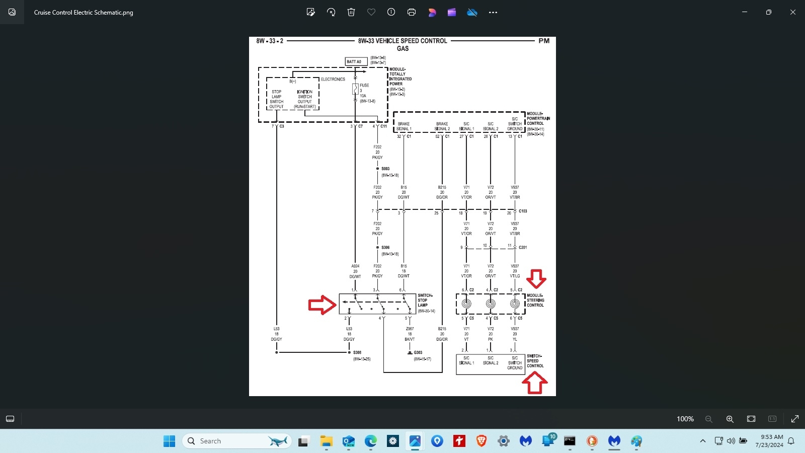
Timing mark verification for the crankshaft. BCM - because of current path of electric running anywhere due to water in the ECU - and the PO572 fault code that is not the fault of the brake switch. What do you think? Something you might have support that could go somewhere? Or spinning my wheels - already worked it to death kind of job? I may have to cut off the sheath of wire wrap and go searching to find if there is evidence of any wires that may have gotten hot enough to melt the insulation off the conductors - But - knowing what to expect on which pins of the present BCM might prove or disprove the need for deep surgery like I may be facing. Yes - a DVOM and doing pin checks has been my efforts since I first learned about the Datsun 280Z fuel systems.
Monday, July 22nd, 2024 AT 5:23 PM

10 Replies

Tiny
RQCOOK
  • MEMBER
  • 10 POSTS
Nearly 9:30 Monday night -
I have thought about all I wrote.
I went back out and started Carol's engine again.
And it starts so nicely - idles up and as it warms up drops down.

I did not tell that -
I have smoked this intake manifold.
I put an A/C vacumn pump on the source end of the vacumn for the brake booster.
And had an extremely easy assist brake pedal effort.
I checked the inside of the supply vacumn nipple on the new intake manifold
And it passed a 1/4" drill bit with no problem.

Why I changed the intake - was because the butterfly flap was once again stuck -
And I believed it was easiest just to change it - rather than try to clean it again.
But as easy as it is -
I can pressure wash the original intake of the deposits off the shaft and bores -
And put it back on in about 45 minutes or so.
I am tempted to do this - just on principles -
That something is influencing the vacumn source for having a hard brake pedal.

Something - if the engine is in time?

Am - I so sure that the engine is not in time?
It seems to start and do what I would expect an engine to do with a new chain/guides and tensioner.

So - tomorrow - if I can get a visual on the crankshaft/serp belt pulley mark to the correct mark on the pointer - then I will pull the valve cover and verify that the cam gear marks - that are near 3 O'clock on the exhaust and near 9 O'clock for the intake. Before I ever consider the rest of the grunt to pull the front cover again.
Considering - I went to lengths to not turn the engine at all - other than to do the dark links on the chain to the dots on the gears - I am having trouble believing it is out of time.
The engine starts too well.

I just can not explain the low vacumn volume.
Hard to believe a booster went bad sitting still.
The electric a/c vacumn pump makes for an easy assist brake pedal.
The hand vacumn pump shows that the diaphram is not leaking - it holds a vacumn.
__________________________________________________________________________________________.

After that -
I guess I would need to focus
On the Po572 -
What voltage to expect coming in to and out of the Brake Light switch.
The brake lights worked prior to all of this.
The brake lights worked just before I went to pickup and install a new switch.
And I certainly will check to see if the brake lights work again - tomorrow.

But the reading I have done - tells me that the brake switch also sends power
to disengage the cruise control - and the electric controlled torque converter.

So - doing a terminal to terminal voltage check and resistance check back to ground
likely would be a starting point there. I do not have that schematic - nor know the location of the cruise control module or it's grounds. But doing a pin by pin - I know to do - I simply do not have the values and terminal points to go directly to - as a plan of action.

If the brake lights work - and they did.
I have no reason to not believe that they will again tomorrow morning.

Then this reply is what I see all over the place -
"DTC P0572 stands for "Brake Switch 'A' Circuit Low.". This code is logged when the brake switch's circuit "A" shows signs of low voltage. This may be set due to brake switch failure, a faulty PCM, or wiring issues. Common symptoms to watch for include brake lights that won't turn on and cruise control."

So -If the brake lights function -
Am I expecting fused B+ power to come down to the switch and go through the switch
for output to the brake light bulbs and in companion send a circuit signal to the cruise control unit to disengage cruise - or is it some different current flow.

And -
If the proper nomenclature - descriptive term is applied by all people -
Which it is not.

Then is the pcm that is referred to - also the Engine Control Unit that I have replaced?

And -
I did not have this P0572 issue - before doing this work.
If it is so - that this control unit is a reflash -
And there is an issue with the control unit - on this one circuit -
Then perhaps this is the core of the PO572 DTC.
_______________________________________________________________________________________.

So - that is my rethink -
Let me know what if any time you might want to give toward this.

Rowan
An iATN member - since 1998.
Was this
answer
helpful?
Yes
No
Monday, July 22nd, 2024 AT 7:09 PM
Tiny
RQCOOK
  • MEMBER
  • 10 POSTS
I found this page.
That shows the timing marks on the serp belt pulley and the pointer on the cover.
And the camshaft timing marks.

https://www.jeeppatriot.com/threads/camshaft-timing.337673/?post_id=1868149&nested_view=1&sortby=oldest#post-1868149

I guess - to focus on the brake light switch circuit issue.
Was this
answer
helpful?
Yes
No
Monday, July 22nd, 2024 AT 7:24 PM
Tiny
RQCOOK
  • MEMBER
  • 10 POSTS
I found this page
That shows an electric schematic for the cruise control.

https://www.jeeppatriot.com/threads/cruise-control-issue-could-anyone-help.343085/

So - I will keep looking, keep checking and looking to trace circuits.
Was this
answer
helpful?
Yes
No
Monday, July 22nd, 2024 AT 8:04 PM
Tiny
RQCOOK
  • MEMBER
  • 10 POSTS
AS water was in the Control Unit mounted on the air filter housing -
And
Water would allow current to travel to the point of least resistance any where.

Replacing the Control unit has allowed the engine to start and run.
+++++++++++++++++++++++++++++++++++++++++++++++++++++++++.

As now - There is a chronic error code with the brake light switch circuit.
P0572

I have reached the point - where I need to identify the wiring configuration
in C1 and C2 of the 2 bulk wire connectors on this control unit.
And
The Integrated power module - which is the lower half of the fuse / power distribution
in the left side of the engine bay.

And -
Do further mind tracing of how -
That the Cruise control fault code could be hard set -
Not to be removed from the memory bank.

So,
I would think that -
The water intrusion - once removed from the picture -
And with a newly flashed Control unit - where C1 and C2 are located
have clean circuits - that things would like themselves.
________________________________________________________________________________________.

Post #9 on this page - shows the lower end of C1 and C2 attaching to
The lower side of the fuse panel / power distribution hub mounted in the
left front fender well - in front of the battery.

https://www.jeeppatriot.com/threads/wiring-harness-connector-and-component-location-diagrams.342288/

And

The component location of the cruise control circuits.

Was this
answer
helpful?
Yes
No
Tuesday, July 23rd, 2024 AT 7:47 AM
Tiny
RQCOOK
  • MEMBER
  • 10 POSTS
So, I put out a help request to the PCM supplier this morning -
Asking if they could identify which of the 2 bulk wire connecters
are P1 - and if they could also show the location of the pins as they
are numbered and colored - in 2 columns.

If the signals are there to the correct pin locations for inputs -
Then I would suspicion that the electronic portion of the "Totally integrated Power Module" a section of the fuse panel - power distribution became burned out when I attempted to start this engine - with water in the PCM wells - P1 and P2.
Was this
answer
helpful?
Yes
No
Tuesday, July 23rd, 2024 AT 7:52 AM
Tiny
RQCOOK
  • MEMBER
  • 10 POSTS
I know I have hit - you the reader with a lot of words - to digest.
I have been chewing on it all - over the last 2 days.

If the PCM supplier says no -
And
Likely even if they do not say anything -
I will attempt to find the wiring configuration and
perform a current path set of tests to and from the brake light switch
to and from the PCM - Including a voltage drop test for the ground on pin 13.

Unless this information - is just simply and readily available to you.
It is not so much easy to find for me.

Yet I will try again - now - before the morning passes.

If the circuit in the Power box is shorted - I need to order today.
If the circuits to and from the brake light switch to the PCM are open -
I need to repair them today.
If the PCM has an open circuit and is a defect - I would like to have proven that - today so that I am not faulted for having caused this condition to have existed.

And
I thank you - for not laughing at me - very hard - this morning.

Rowan Cook
Was this
answer
helpful?
Yes
No
Tuesday, July 23rd, 2024 AT 7:59 AM
Tiny
KEN L
  • MASTER CERTIFIED MECHANIC
  • 45,347 POSTS
Hi Rowan,

You have done a lot of work, do the people at Itan give you wiring diagrams, it seems like that is the place to go for problems like this? Does anyone at Itan help you? If not here is a guide to help you with the testing and I have included the engine and PCM wiring diagrams so you can do some testing.

https://www.2carpros.com/articles/how-to-check-wiring

I can also tell you I have seen a problem with the TIPM in these cars that can create strange problems. Check out the images (below). Let us know how it goes.
Was this
answer
helpful?
Yes
No
Tuesday, July 23rd, 2024 AT 9:40 AM
Tiny
RQCOOK
  • MEMBER
  • 10 POSTS
I gave up paying as a sponsoring member - some years ago.
I have all but retired -
But this vehicle is my wife's -

And I simply began this last week -
To make sure that if there was problems in the timing chain area -
or water pump - or other rotating shafts of the serp belt and bearings -
That I handled them while the weather was warmer rather than laying down out in rain,
or snow in winter weather.

Water intrusion into the PCM wells of C1 and C2 brought all of this on.
I reattached the 2 bulk wire connectors to the PCM
with water in the pinched jacket cover -

And attempted to start this engine.

I knew I was in trouble.
I just had no real idea - how deep the quagmire was going to be.
_______________________________________________________________________.

I would have to again upgrade my iATN membership to be a sponsoring member
for anyone to give any suggestions.

Instead - I bought the complete wiring harnass diagram of this vehicle -
And have resolved to do pin checks -
Of what is common and attempt to not kill ourselves in parts costs.
_______________________________________________________________________.

I have been interacting with CoPIlot AI -
And that being - does not have the ability to interact with facts or schematics -
Only logic and fake empathy for the pain that I am living through.
___________________________________________________________________.

Since this morning -
Armed with schematic -
I identified one of the power wires that was supposed to be B+ hot at all times -
And it was not so.
I did what I needed to put a fused B+ on that wire -

And it brought about
permanent fault codes for the MAP, TPS and CTS sensors.

AI suggests that these 3 sensors have a 5v voltage signal being sent out to the 3.
I don't know if -
AI is talking out it's perverbial butt - based upon other search results or not.
But - I will study it as well as I have the heart - until my head of steam just goes flat.

I have ordered a replacement fuse box / power distribution -
And that is likely Friday or Monday.

I am thankful for our problems.
Giving glory to one one person who can empower a process to work through to have answers. Very thankful for problems such as these.

I could not do this - with out help.

These troubles help me to reman humble.

Rowan
Was this
answer
helpful?
Yes
No
Tuesday, July 23rd, 2024 AT 1:32 PM
Tiny
RQCOOK
  • MEMBER
  • 10 POSTS
I did not tell you - but since I powered up that green wire on the C - brake light switch circuit - the ABS has locked up the brakes. The vehicle will not go forward or backward - without a great deal of strain. So, I will detach the ABS wire from the module and see if the wheels are now free.

And rest -
And start again on another day.

Rowan
Was this
answer
helpful?
Yes
No
Tuesday, July 23rd, 2024 AT 1:35 PM

Please login or register to post a reply.

Sponsored links