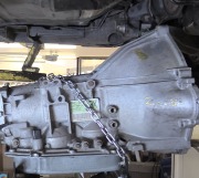
Hello - John
Here is the info you requested. . ..good luck
I have attached the Technical Service Bulletin on bleeding.
Bulletin No.: 01-07-31-002B
Date: November 01, 2006
INFORMATION
Subject:
Improved Bleeding Procedure for Hydraulic Clutch Release System
Models:
2007 and Prior GM Passenger Cars and Light Duty Trucks (including Saturn)
2007 and Prior Chevrolet and GMC 6-7F T-Series Medium Duty Tilt Cab Models
2007 and Prior Isuzu F-Series Medium Duty Tilt Cab Models
2006-2007 HUMMER H3
Supercede:
This bulletin is being revised to add model years. Please discard Corporate Bulletin Number 01-07-31-002A (Section 07 - Transmission/Transaxle). This bulletin is being issued to inform dealers of an improved procedure to aid in the ease of bleeding the clutch hydraulic system for the above listed vehicles. This procedure can be used anytime air is introduced into the hydraulic system. Following this procedure may also reduce the number of unnecessary parts replaced for low clutch pedal reserve and high shift effort.
Verify that all the lines and fittings are dry and secure.
Clean the dirt and grease from the reservoir cap in order to ensure that no foreign substances enter the system.
Remove the reservoir cap.
Fill the reservoir to the proper level with the required fluid.
Attach the J 43485 (Adapter) to the J 35555 (Mity Vac), or equivalent.
Brake fluid will deteriorate the rubber on J 43485. Use a clean shop cloth to wipe away the fluid after each use.
Place and hold the adapter on the reservoir filler neck to ensure a tight fit. In some cases, the adapter will fit into the reservoir opening.
Apply a vacuum of 51-68 kPa (15-20 hg) and remove the adapter.
Refill the reservoir to the proper level.
Repeat Steps 6 and 7.
If needed, refill the reservoir and continue to pull a vacuum until no more bubbles can be seen in the reservoir or until the fluid level no longer drops.
The vehicle will move if started in gear before the Actuator Cylinder is refilled and operational. Start the vehicle the first time in neutral to help prevent personal injury from vehicle movement and see if the transmission will shift easily into gear.
Pump the clutch pedal until firm (to refill actuator cylinder).
Add additional fluid if needed.
Test drive vehicle to ensure proper operation
Clutch Bleed Procedure - Read Before Attempting Any Service
DO NOT ATTEMPT TO BLEED THE CLUTCH HYDRAULIC UNIT.
According to the manufacturer, the hydraulic system (mater cylinder, actuator, hose) is serviced as a COMPLETE UNIT. It has been filled with fluid and bled of air at the factory. If the system requires any fluid, check the hydraulic components for leakage. Remove the slave cylinder from the clutch housing and check for leakage at the piston, a slightly wet surface is normal. If excessive, replace system.
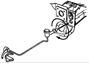
Individual components of the system are not available for service, except the slave cylinder actuator pushrod plastic retainer strap. Do not attempt to bleed the clutch hydraulic system. The bleed screw located on the clutch hydraulic slave cylinder is used for the factory fluid fill only.
Use only DOT 3 brake fluid. Do not use mineral oil or a paraffin base oil in the hydraulic system as damage to rubber parts will occur. Clean the cap and sides of reservoir before removing cap, then remove diaphragm. Carefully replace diaphragm and cover after filling.
Hydraulic Clutch Control System
IMPORTANT: The clutch hydraulic system is to be serviced as a COMPLETE UNIT!!!. It is a sealed unit and has been filled with fluid and bled of air at the factory. Individual components of the system are not available for service, except the slave cylinder actuator pushrod plastic retainer strap. Do not attempt to bleed the clutch hydraulic system. The bleed screw located on the clutch hydraulic slave cylinder is used for the factory fluid fill only.
WARNING: Do not attempt to bleed the clutch hydraulic unit. Any observed fittings are there for factory use only. The unit comes as a complete pre-bled unit.
REMOVAL
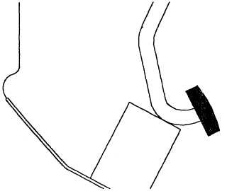
Block clutch pedal up to prevent pedal from being depressed with slave cylinder removed from transaxle.
Remove air induction system.
Disconnect negative battery cable from battery.
Disconnect positive battery cable from battery
Remove hold-down retaining nut and screw, and lift off battery hold-down retainer.
Lift the battery of vehicle, and place in a safe location.
Remove battery tray bolts and tray. IMPORTANT: One bolt is located in the fender well.
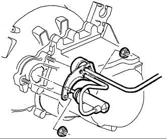
NOTICE: Removal of the hydraulic damper with a power tool prior to removal of the actuator could result in breaking off the hydraulic line.
IMPORTANT: Prior to removing the slave cylinder from the clutch housing, make sure that the clutch hydraulic system has sufficient fluid. Refer to the "Clutch Hydraulic Fluid Check" procedures in this manual. (This is not necessary if the clutch hydraulic system is being removed to be replaced.)
Rotate actuator 1/4 turn counterclockwise while pushing toward housing in order to disengage the bayonet connector and remove from clutch housing.
Remove two hydraulic damper to clutch housing nuts and slide damper and bracket assembly off studs.
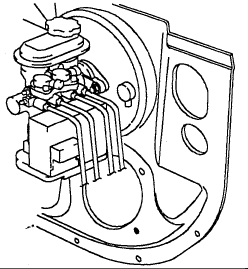
ABS equipped vehicles, remove brake master cylinder-to-booster nuts. NOTICE: ABS equipped vehicles require the brake master cylinder to be moved off booster studs and moved slightly towards the engine to allow removal of the clutch hydraulic master cylinder. Use care not to bend or kink brake lines.
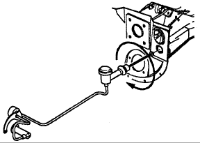
Remove clutch master cylinder pushrod retainer clip from clutch pedal pin and disconnect pushrod from pedal.
Turn clutch master cylinder approximately 1/8 turn clockwise and remove from dash.
Remove hydraulic system from vehicle.
INSTALLATION
IMPORTANT: When installing a new unit, the plastic retainer straps on the actuator remain in place when installing the unit. This will ensure the actuator rod is seated in the clutch release fork pocket as the actuator is installed.
IMPORTANT: When installing an existing unit, a new plastic retainer strap should be installed on the end of the pushrod and the straps should be attached to the actuator.
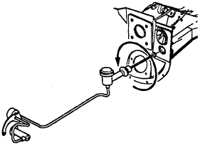
Install clutch master cylinder into dash with reservoir leaning outboard. Turn approximately 1/8 turn counterclockwise to lock in position.
On ABS equipped vehicles, place the brake master cylinder back on the booster studs and tighten brake master cylinder-to-booster nuts.
Torque:27 N.m (20 ft. lbs.) .
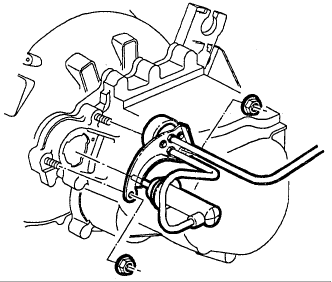
Slide damper and bracket onto clutch housing damper studs and install nuts.
Torque:25 N.m (18 ft. lbs.) .
Install actuator into clutch housing with hydraulic line facing down and rotate actuator 1/4 turn clockwise while pushing toward housing.
Add dielectric (silicone) grease to clutch pedal pin then connect pushrod and install pushrod retainer clip to clutch pedal pin.
Install battery tray.
Torque battery tray bolts.
Make sure battery tray is clean.
Make sure that the battery cable ends are clean and free of corrosion. (Clean with a wire brush.)
Make sure that the battery is in good physical condition (e.g., no cracks, or obvious damage) and that the terminals are clean.
Install battery carefully in the battery tray; make sure that the terminals do not short against any metal during the installation.
Install battery hold-down retainer, locking the battery into the tray. Install and tighten the hold-down retainer nut and screw.
Install the positive battery cable first.
Torque:17 N.m (151 inch lbs.) .
Install the negative battery cable last.
Torque:17 N.m (151 inch lbs.) .
Install air induction system.
Tuesday, November 4th, 2008 AT 1:30 PM


