Two inputs turn on one or both of the fans in the low or high mode determined by the PCM. The A/C pressue fan switch, and the Coolant Temperature Sensor. Both of these send signals to the PCM to control both fans. The PCM controls the fans power thru a low speed coolant fan relay, and a high speed coolant fan relay. There are two coolant fan resistors between the two fans, and these set the speeds for the fans to run based on PCM output.
Here is the D/O from the manual.
Description and Operation
Two Coolant Fans, wired in parallel, operate whenever cooling is required.
The Powertrain Control Module (PCM) has two Coolant Fan terminals: one for high speed and one for low speed. When the PCM's low speed control closes at connector C3, terminal C4, it grounds the Low Speed Coolant Fan Relay coil. When the Ignition Switch is in the RUN position and the relay contacts close, voltage is supplied to the Coolant Fans. The Coolant Fan Resistors drop the voltage to the LH Coolant Fan, causing it to run in low speed. The RH Coolant Fan also runs, but at high speed because the Coolant Fan Resistors are bypassed. The PCM's low speed output is turned on when coolant temperature reaches 100°C (212°F).
High speed operation is similar to that of low speed. When coolant temperature reaches 108°C (226°F), the PCM's high speed control closes at connector C3, terminal C3, grounding the High Speed Coolant Relay coil. The relay contacts close and both fans run at high speed since the PCM's low speed control remains closed. When A/C head pressure reaches 1445 kPa (210 psi), the A/C Pressure Fan Switch closes, grounding the PCM input connector C1, terminal D9. This also causes the PCM high speed control to close, and both Coolant Fans run at high speed.
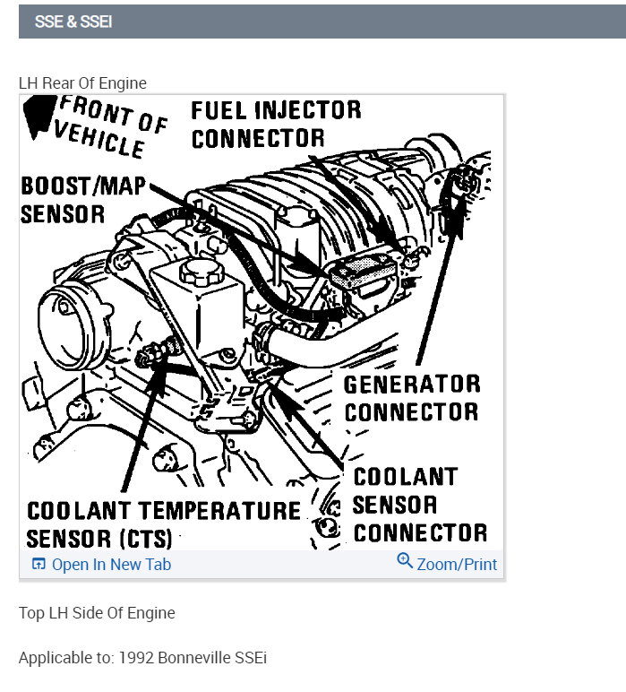
The radiator fan is controlled by the engine coolant sensor here is the location in the images below.
Image (Click to make bigger)
Wednesday, August 16th, 2006 AT 4:02 PM
