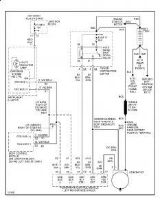
TEST TC-6A: CHARGING SYSTEM VOLTAGE TOO HIGH
Ensure battery is fully charged and generator belt is in good condition and properly adjusted before proceeding. Turn ignition on.
Using scan tool, actuate generator field driver. Using voltmeter, check voltage by backprobing terminal No. 2 (Dark Green wire) in the round 2-wire connector at rear of the generator.
If voltage cycles from low voltage to high voltage, perform TEST TC-6B . If voltage does not cycle from low voltage to high voltage, go to next step.
Using scan tool, stop actuation of generator field driver. Turn ignition off. Disconnect connectors from Powertrain Control Module (PCM). The PCM is located between driver's side front fender and power distribution center, near battery.
Disconnect round 2-wire connector from rear of generator. Using ohmmeter, check resistance between ground and PCM connector terminal No. 8 (Dark Green wire) on 2.4L, 3.3L and 3.8L, or terminal No. 4 (Dark Green wire) on 3.0L.
If resistance is 5 ohms or more, go to next step. If resistance is less than 5 ohms, repair generator field driver circuit for short to ground in Dark Green wire between PCM and generator. Perform TEST VER-2A .
Using ohmmeter, check resistance between ground and generator field driver terminal in the generator. This is the terminal on rear of generator that the Dark Green wire in the round 2-wire connector fits on.
If the resistance is less than 5 ohms, short circuit exists in the generator. Repair or replace generator as necessary. Perform TEST VER-2A . If the resistance is 5 ohms or more, replace PCM. Perform TEST VER-2A .
TEST TC-6B: CHARGING SYSTEM VOLTAGE TOO HIGH
Using scan tool, stop actuation of generator field driver. Note the target charging voltage. If target charging voltage is 13 volts or less, go to next step. If target charging voltage is more than 13 volts, go to step 4).
Using scan tool temperature probe, measure underhood temperature near the Powertrain Control Module (PCM). The PCM is located between driver's side front fender and power distribution center, near battery. Using scan tool, read temperature of the battery temperature sensor.
If temperature of the battery temperature sensor is not within 10 degrees of the underhood temperature, replace PCM. Perform TEST VER-2A . If temperature of the battery temperature sensor is within 10 degrees of the underhood temperature, go to next step.
Start engine and maintain engine at 1600 RPM. Using scan tool, read target charging voltage and charging voltage. Compare the 2 readings for 5 minutes.
If difference between the 2 readings is more than one volt, replace PCM. Perform TEST VER-2A . If difference between the 2 readings is one volt or less, allow engine to idle. Shut engine off. Turn ignition on. Using scan tool, clear Diagnostic Trouble Codes (DTCs) from PCM
TEST VER-2A: ROAD TEST VERIFICATION
NOTE:For connector terminal identification, see CONNECTOR IDENTIFICATION under INTRODUCTION in TESTS W/CODES article in the ENGINE PERFORMANCE Section.
Inspect vehicle to ensure all engine components are connected. Reassemble and reconnect components as necessary.
Check if initial symptom still exists. If initial or another symptom exists, repair is not complete. Check for Technical Service Bulletins (TSBs) that apply to the symptom and return to DTC TEST , if necessary.
If any DTCs have not been diagnosed, go to DTC TEST and finish diagnosing remaining DTCs as necessary. If all DTCs have been diagnosed, go to next step.
If Powertrain Control Module (PCM) has not been changed, using scan tool, clear DTCs from PCM. Using scan tool, reset all values in adaptive memory. Disconnect scan tool. To ensure no other DTCs remain, go to next step.
Using scan tool, check for stored DTCs. If repaired DTC has reset, repair is not complete. If another DTC exists, return to DTC TEST and follow path specified by other DTC. If no other DTCs exist, repair is now complete.
SPONSORED LINKS
Thursday, July 30th, 2009 AT 6:42 AM

