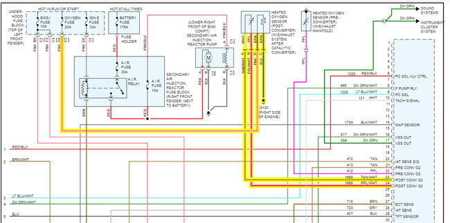
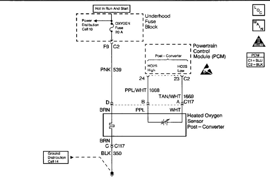
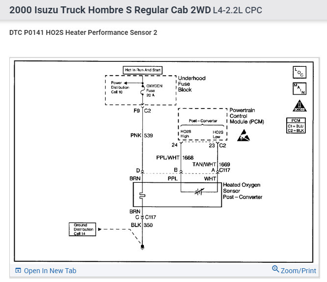
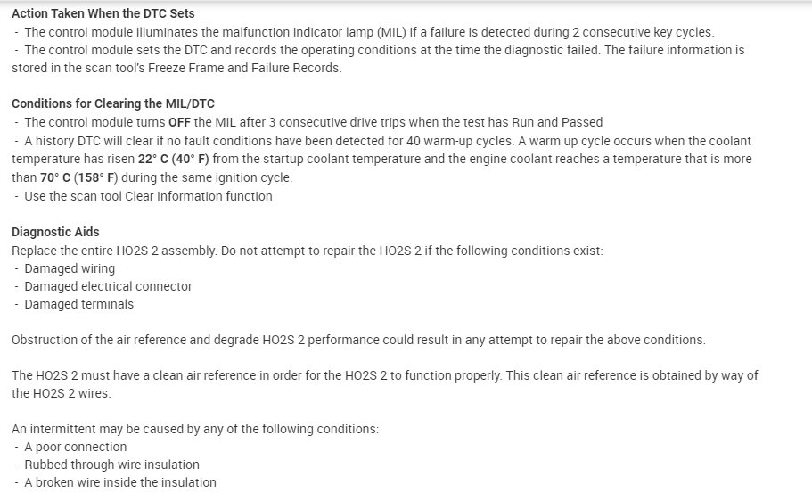
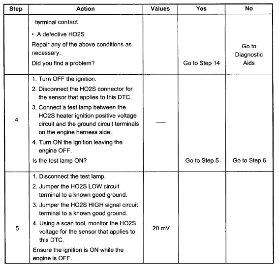
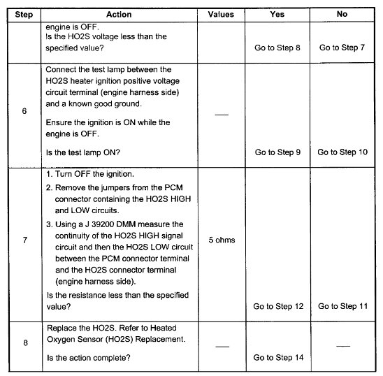
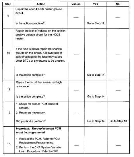
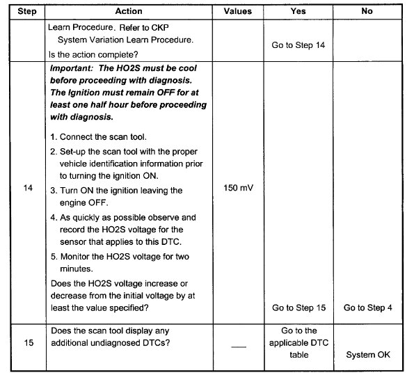
This is for Bank 1 sensor 2. At one point the sensor had been replaced.
I have Thorley checked current and voltage on the heater circuit.
I've also changed out the engine control unit with absolutely no change.
I'm a 67-year-old EE, my specialty is embedded systems.
I have a few diagnostic software tools one is torque and the other I can't remember the name.
I'm using a wireless Bluetooth ODB module as well as a lab digital oscilloscope.
Here comes the part I don't understand, with the oscilloscope attached to ground and the bank one sensor 1 02 sensor I have perfectly good waveforms well within specification, everything looks great.
When I attach the oscilloscope to bank one sensor 2 which is to isolated wires going to the engine control unit neither one is ground that I'm aware of they both go directly to the engine control unit I get perfectly what looks to be perfectly good waveforms that are a little slower and lag.
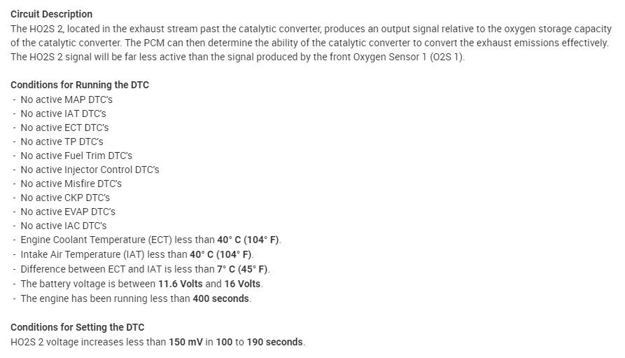
I've made these measurements a few times they are quite repeatable. When the dongle is connected to the vehicle and the vehicle is running the diagnostic software indicates that Bank one sensor one is functioning normally the graph is normal, everything about it looks normal, However the diagnostic software indicates that Bank one sensor 2 has no activity and the voltage around is ~.6 V, the graph indicates the same thing flat line ~.6 V. I've connected the scope right at the pins on the engine control unit. I have checked the connections between the wires leading to the engine control unit and the PCB inside the engine control unit.
My question is, how can I actually have electrical activity on bank one sensor 2 and the diagnostic software does not report any activity, is this a function of the software within the engine control unit?
What the heck do I do now?
Saturday, October 8th, 2022 AT 5:43 PM
