Sunday, January 10th, 2021 AT 12:06 PM
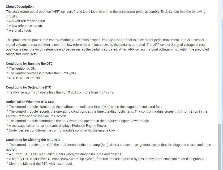
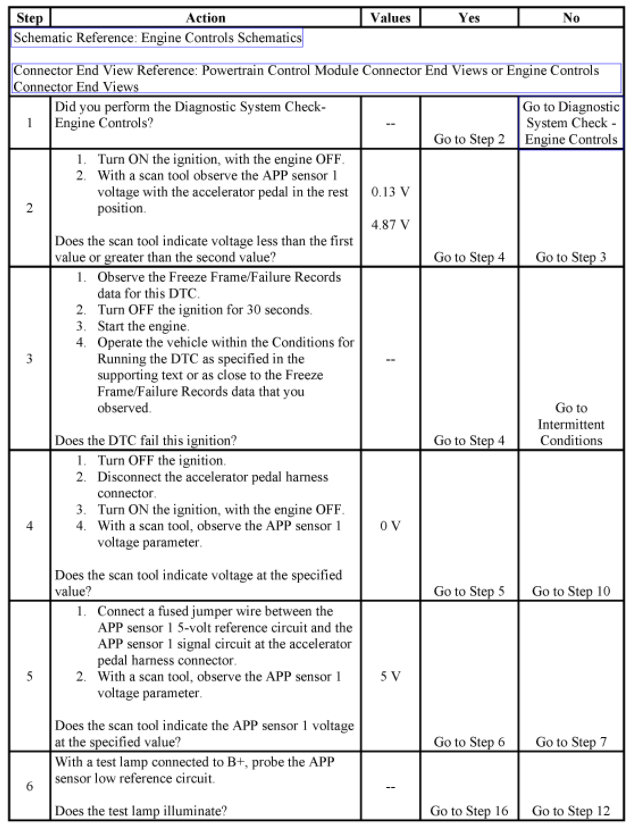
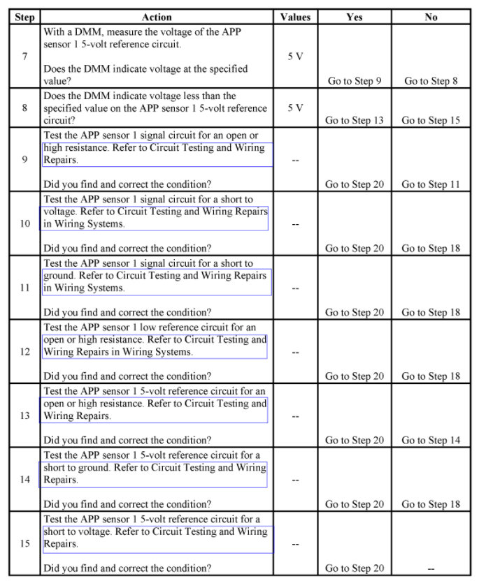
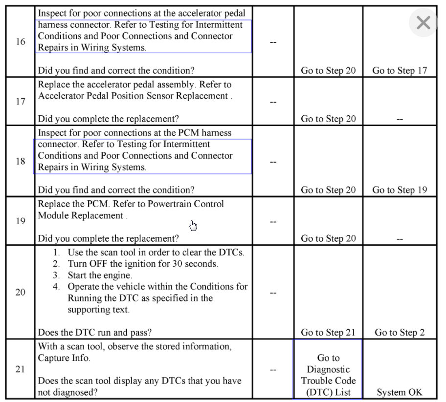
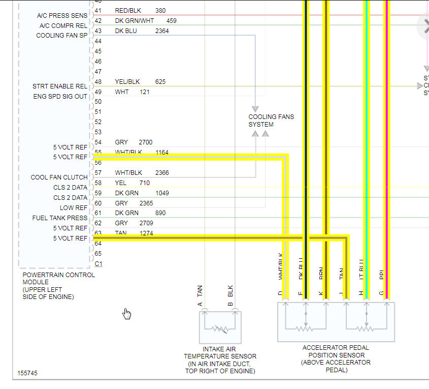
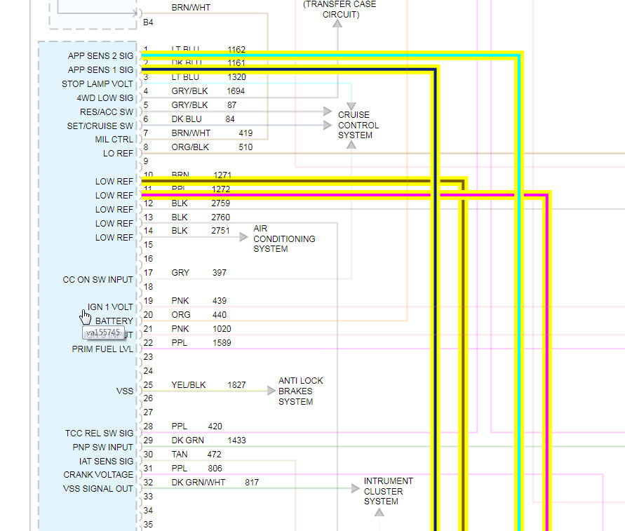
Just installed a new fuel pump, now there's no throttle response when I push down the pedal. Starts and idles fine. But pump the gas, , othing. I've replaced the APP sensor (only to find out the old one was fine) as is the new one. Had an electrician come hook up to it, told me to check multiple wires. Specifically the ones to the TB and the APP. Both getting 5v. The wires on the ECU for the TB/APP are also getting 5v. So why am I getting these codes? And why doesn't the engine rev when I hit the gas? The Reduced Engine Power light is on, as well as the Service Engine Soon light, and it's throwing codes P1275 and P1635 Going crazy, please help. TIA
