It is not going to be an inline fuse. If it was then there would be no power to anything. The closest code I found was P0885 relay circuit malfunction. The relay would be the most likely faulty component not supplying power to the solenoids. Here is the fault tracing procedure:
Collision
� 23
2006 Hyundai Truck Tucson
�
V6-2.7L
�
�
Automatic Transaxle (F4A42)
Vehicle� ALL Diagnostic Trouble Codes ( DTC )� Testing and Inspection� P Code Charts� P0885� Automatic Transaxle (F4A42)
AUTOMATIC TRANSAXLE (F4A42)
DTC P0885 A/T RELAY CIRCUIT MALFUNCTION
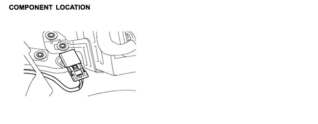
COMPONENT LOCATION
Open In New TabZoom/Print
GENERAL DESCRIPTION
� The HIVEC Automatic Transmission supplies the power to the solenoid valves by way of a control relay. When the TCM sets the relay to ON, the relay operates and the battery power is supplied to all the solenoid valves. When the TCM sets the relay to OFF, all solenoid valve power is shut off and the transmission is held in the 3rd gear position. (Fail Safe Mode)
DTC DESCRIPTION
� The TCM checks the A/T control relay signal by monitoring the control signal. If, after the ignition key is turned on, an unexpected voltage value, which is quite a bit lower than battery voltage is detected, the TCM sets this code.
DTC DETECTING CONDITION
DTC DETECTING CONDITION
Open In New TabZoom/Print
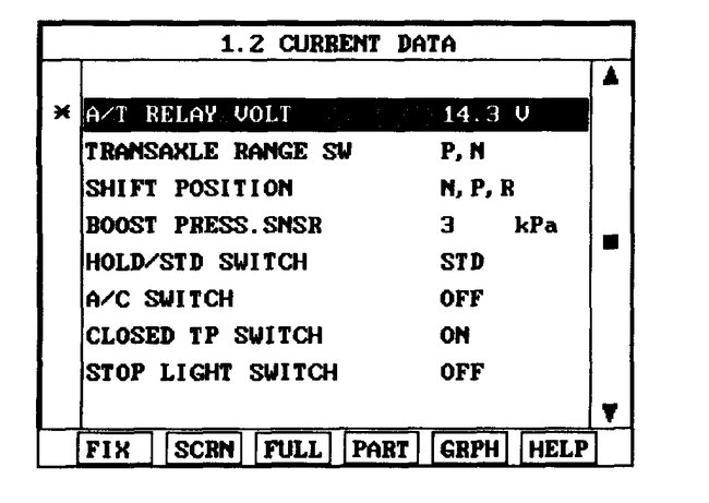
MONITOR SCAN TOOL DATA
� 1.� Connect scan tool to data link Connector (DLC),
� 2.� Ignition ON & Engine OFF.
Open In New TabZoom/Print
� 3.� Monitor the A/T, CON. RELAY VOLT parameter on the scan tool.
� � � � Specification: Approximately B+
� 4.� Is A/T RELAY VOLT within specifications?
� � � � YES
� � � � � � Fault is intermittent caused by poor contact in the sensor's and/or TCM (PCM)'s connector or was repaired and TCM (PCM) memory was not cleared. Thoroughly check connectors for looseness, poor connection, bending, corrosion, contamination, deterioration or damage. Repair or replace as necessary and go to Verification of Vehicle Repair procedure.
� � � � NO
� � � � � � Go to Terminal & Connector Inspection procedure.
TERMINAL & CONNECTOR INSPECTION
� 1.� Many malfunctions in the electrical system are caused by poor harness and terminals. Faults can also be caused by interference from other electrical systems, and mechanical or chemical damage.
� 2.� Thoroughly check connectors for looseness, poor connection, bending, corrosion, contamination, deterioration, or damage.
� 3.� Has a problem been found?
� � � � YES
� � � � � � Repair as necessary and then go to "Verification of Vehicle Repair procedure.
� � � � NO
� � � � � � Go to Power Supply circuit inspection procedure.
POWER SUPPLY CIRCUIT INSPECTION
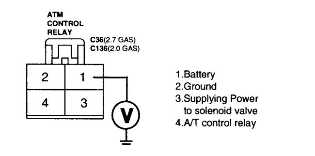
� 1.� Ignition ON & Engine OFF.
� 2.� Disconnect the A/T CONTROL RELAY connector.
Open In New TabZoom/Print
� 3.� Measure the voltage between terminal 1 of the A/T CONTROL RELAY harness connector and chassis ground.
� � � � Specification: Approximately B+
� 4.� Is voltage within specifications?
� � � � YES
� � � � � � Go to Signal circuit inspection procedure.
� � � � NO
� � � � � � Check that A/T-30A Fuse in engine room junction is installed or not blown.
� � � � � � Check for Open in harness. Repair as necessary and Go to "Verification of Vehicle Repair" procedure.
SIGNAL CIRCUIT INSPECTION
Specification
Open In New TabZoom/Print
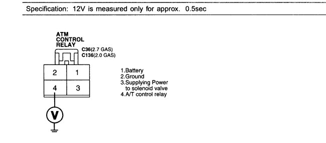
� 1.� CHECK A/T control relay harness
� � � � 1)� Ignition OFF.
� � � � 2)� Disconnect the A/T CONTROL RELAY connector.
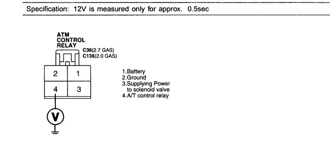
� � � � 3)� Measure the voltage between terminal 4 of the A/T CONTROL RELAY harness connector and chassis ground.
Specification
Open In New TabZoom/Print
� � � � 4)� Turn ignition switch OFF -ON.
� � � � � � � Specification:� 12 Volts� is measured only for� approximately 0.5 seconds
� � � � 5)� Is voltage within specifications?
� � � � � � � YES
� � � � � � � � � Go to Check Supplying Power to solenoid valve procedure.
� � � � � � � NO
� � � � � � � � � Check for open in harness. Repair as necessary and Go to Verification of Vehicle Repair procedure. If signal circuit is OK, Substitute with a known-good PCM/TCM and check for proper operation. If the problem is corrected, replace PCM/TCM and then go to "Verification of Vehicle Repair" procedure.
Specification
Open In New TabZoom/Print
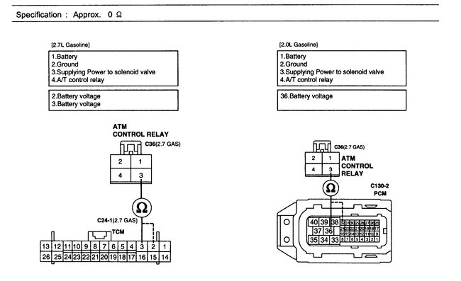
� 2.� CHECK Supplying Power to solenoid valve harness
� � � � 1)� Ignition OFF.
� � � � 2)� Disconnect the A/T CONTROL RELAY and PCM/TCM connector.
� � � � 3)� Measure the resistance between terminal 3 of the A/T CONTROL RELAY harness connector and terminal 2, 3 of the PCM/TCM harness connector.
� � � � � � � Specification:� Approximately 0 Ohms
� � � � 4)� Is resistance within specifications?
� � � � � � � NO
� � � � � � � � � Go to Ground circuit inspection procedure.
� � � � � � � � � Check for Open in C-35 (2.7 GAS) joint connector.
� � � � � � � � � Check for open in harness. Repair as necessary and Go to "Verification of Vehicle Repair" procedure.
GROUND CIRCUIT INSPECTION
� 1.� Ignition OFF.
� 2.� Connect the A/T CONTROL RELAY connector.
Specification
Open In New TabZoom/Print
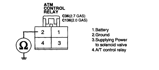
� 3.� Measure the resistance between terminal 2 of the A/T CONTROL RELAY harness connector and chassis ground.
� � � � � � � Specification:� Approximately 0 Ohms
� 4.� Is resistance within specifications?
� � � � YES
� � � � � � Go to Component inspection procedure.
� � � � NO
� � � � � � Check for open in harness. Repair as necessary and Go to Verification of Vehicle Repair procedure.
COMPONENT INSPECTION
� 1.� Ignition OFF.
� 2.� Remove A/T CONTROL RELAY
Open In New TabZoom/Print
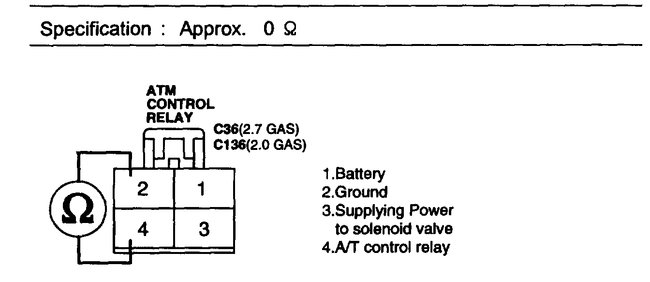
� 3.� Measure the resistance between each terminal of the sensor.
� � � � Specification:
Specification
Open In New TabZoom/Print
� 4.� Is resistance within specification?
� � � � YES
� � � � � � Thoroughly check connectors for looseness, poor connection, bending, corrosion, contamination, deterioration, or damage. Repair or replace as necessary and then go to Verification of Vehicle Repair procedure.
� � � � NO
� � � � � � Replace ATM CONTROL RELAY and then go to Verification of Vehicle Repair procedure.
VERIFICATION OF VEHICLE REPAIR
� After a repair, it is essential to verify that the fault has been corrected.
� 1.� Connect scan tool and select Diagnostic Trouble Codes (DTCs) mode.
� 2.� Using a scan tool, Clear DTC.
� 3.� Operate the vehicle within DTC Enable conditions in General information.
� 4.� Are any DTCs present?
� � � � YES
� � � � � � Go to the applicable troubleshooting procedure.� See: A L L Diagnostic Trouble Codes ( DTC ) > Diagnostic Trouble Code Descriptions > Transmission
� � � � NO
� � � � � � System performing to specification at this time.
Images (Click to make bigger)
Friday, November 22nd, 2019 AT 11:10 PM
