Hello. thanks for the donation ... much appreciated
Hope this helps .. let me know !
IGNITION SWITCH ASSEMBLY
Removal & Installation
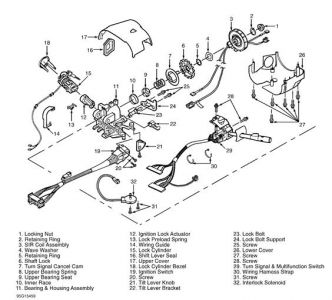
Remove upper and lower covers. See UPPER & LOWER COVERS . Disconnect steering column electrical connector. Remove 2 wiring harness straps securing steering column wiring harness. Disconnect steering column electrical connector from vehicle wiring harness. Remove ignition switch harness from wiring harness strap.
Disconnect Gray and Black turn signal and multifunction switch connectors from column connector. Remove mounting screws and ignition switch assembly. To install, reverse removal procedure. Tighten ignition switch mounting screws to specification. See TORQUE SPECIFICATIONS .
LOCK CYLINDER (FUNCTIONAL), IGNITION LOCK ACTUATOR & LOCK BOLT
Removal & Installation (Lock Cylinder)
Remove upper cover. See UPPER & LOWER COVERS . On floor shift models, remove pivot and pulse switch for access to PASS-Key II(R) wiring. See PIVOT & PULSE SWITCH . On all models, turn lock cylinder to RUN position. Press locking button on back of bearing and housing assembly. Remove lock cylinder and let it hang free. Remove lock preload spring.
Disconnect steering column electrical connector. Disconnect Gray turn signal switch connector from column connector. Remove 17-way secondary lock. Disconnect pass key terminals (if equipped) from cavities No. 16 and 17. Remove pass key wiring harness from wiring harness straps. Remove wiring protector and lock cylinder.
To install, ensure sector is in RUN position. With key in lock cylinder, align locking tab with housing and press into position. Install lock preload spring. To complete installation, reverse removal procedure.
Removal (Ignition Lock Actuator & Lock Bolt)
Remove lock cylinder, and let it hang free. PASS-Key II(R) wiring does not need to be removed. Using needle-nose pliers, remove ignition lock actuator from upper housing assembly.
Remove lower cover. See UPPER & LOWER COVERS . Remove SIR coil assembly. See AIR BAG RESTRAINT SYSTEM article. Using Lock Plate Compressor (J-23653-SIR), push down shaft lock and remove shaft lock retaining ring. Discard retaining ring. Remove shaft lock. Remove 2 screws and lock bolt support bracket. Remove lock bolt.
Installation
Install lock bolt. When installing lock bolt support bracket, tighten upper screw first. Tighten lock bolt support bracket screws to specification. See TORQUE SPECIFICATIONS .
To install shaft lock, align inner block tooth of lock plate to block tooth of steering shaft assembly (non-tilt column) or to block tooth of race and upper shaft assembly (tilt column). Lubricate with synthetic grease. Using Lock Plate Compressor (J-23653-SIR), push down shaft lock and install NEW retaining ring. Ensure retaining ring is firmly seated in groove on shaft.
To install ignition lock actuator, ensure lock bolt is flush with support bracket. Insert lock actuator into upper housing. Rotate actuator counterclockwise until it pushes out lock bolt and actuator seats into housing assembly. Rotate actuator clockwise to RUN position. To complete installation, reverse removal procedure.


SPONSORED LINKS
Monday, April 6th, 2009 AT 5:00 AM

