Hi wagsk1,
Thank you for the donation.
Here is a schematics for the cooling fans.
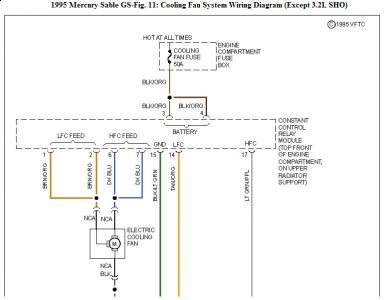
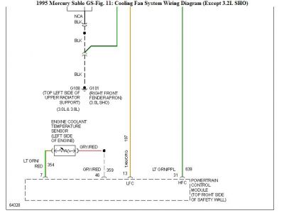
Check through the following and see if you can come up with anything.
ELECTRIC COOLING FAN FUNCTION CHECK
1. Start engine. On models with A/C, turn A/C on. Ensure A/C clutch engages. On models without A/C, run engine until cooling fan begins to operate. If cooling fan(s) do not operate at any fan speed, perform QUICK TEST .
2. If a trouble code is indicated while performing QUICK TEST, perform appropriate test. If after performing QUICK TEST, a Code 111 (pass code) is displayed and no other codes exist, go to next step.
3. Enter output state Diagnostic Test Mode (DTM). See ADDITIONAL SYSTEM FUNCTIONS . Once output state DTM has been entered, ensure all outputs are off. Depress throttle (near wide open). Wait for Malfunction Indicator Light (MIL) to flash once (about 10 seconds). Release throttle.
4. Cooling fan should run at low speed (LFC). Depress throttle to turn fan off. Depress throttle again. Wait until MIL flashes 2 consecutive times (about 15 seconds). Release throttle. Cooling fan should run at high speed (HFC).
Exit output state DTM. If cooling fan(s) do not operate as specified, perform appropriate test. If cooling fans operate as specified and vehicle is equipped with A/C, check A/C Pressure Switch (ACPSW).
QUICK TEST
NOTE: Procedure given is for reading codes using an analog volt-ohmmeter. When using a scan tester, use tool manufacturer's instructions.
Turn ignition off. Set VOM at 0-15V DC range. Connect positive lead of VOM to positive battery terminal. Connect negative VOM lead to Self-Test Output (STO) terminal of Data Link Connector (DLC).
Connect timing light, and go to KOEO SELF-TEST . Activate KOEO SELF- TEST by connecting jumper wire from Self-Test Input (STI) pigtail to Signal Return (SIG RTN) terminal of DLC with ignition on.
ADDITIONAL SYSTEM FUNCTIONS
Output State Diagnostic Test Mode (DTM)
Output state DTM is used as an aid in servicing output actuators associated with EEC-IV system. It allows technicians to energize and de-energize most system output actuators on command. This mode is entered from KOEO SELF-TEST after all codes have been retrieved.
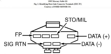
Disconnect cruise control servo (if equipped). With DVOM on 20-volt scale, connect DVOM negative lead to STO/MIL terminal at Diagnostic Link Connector (DLC). See Fig. 1 . Connect positive lead to positive battery terminal. Connect a jumper wire from Self-Test Input (STI) pigtail to Signal Return (SIG RTN) terminal at Diagnostic Link Connector (DLC). Turn ignition on.
Perform KOEO SELF-TEST until continuous memory test is complete. DVOM will read less than 1.0 volt when test is complete. Depress and release throttle. If voltage increases, output state DTM has been entered. If voltage does not increase, depress throttle to WOT and release. If STO voltage still does not increase, go to CIRCUIT TEST QC.
Saturday, April 25th, 2020 AT 12:40 PM


