Hi and thanks for using 2CarPros. Com.
I did some checking and found a technical service bulletin (TSB) related to spark knock. It indicates a problem with the ignition wire routing. If the wires are not properly routed, they can cross spark causing a pinging. Here are the directions for routing. Check to make sure there is no indication of a spark issue and that the wires are properly routed. If this does not help, let me know. All attached pictures correlate with these directions.
_______________________________________
IGNITION SYSTEM - CROSS FIRE/IGNITION WIRE INDUCTION
Related Links
Repair Procedure
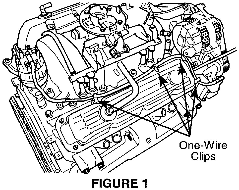
1. Coil Wire Routing (Figure 1 and 2)
A. Remove the coil wire from the distributor cap coil wire tower terminal.
B. Remove the coil wire from the rear five-wire clip, the center three-wire clip, and the front one-wire clip located along the lower side of the right valve cover.
C. Install three (3) one-wire clips p/n 56028186 along the top and front of the valve cover. Use the studs of the valve cover retaining bolts (Figure 1).
NOTE:
SOME APPLICATIONS MAY ONLY HAVE STUD LOCATIONS FOR 3 OF THE ONE-WIRE CLIPS.
D. Route the coil wire starting from the ignition coil toward the distributor. Any excess wire should end up at the distributor end.
E. Install the coil wire into the one-wire clips. This procedure may be easier to perform while the coil wire is loose from the valve cover (before the one-wire clips are attached to the valve cover studs).
F. Cut the ignition wire convolute p/n 04364375 into three lengths 203 mm (8 in.), 101.5 mm (4 in.), And 82.5 mm (3.25 in.).
G. Slit and install the three sections of convolute onto the coil wire between the one-wire clips. Install the 82.5 mm (3.25 in.) Section at the front of the right valve cover. Install the 203 mm (8 in.) And the 101.5 mm (4 in.) Sections along the top side of the right valve cover. This procedure may be easier to perform while the coil wire is loose from the valve cover (before the clips are attached to the valve cover studs).
H. Route the distributor end of the coil wire down and behind the intake manifold, in front of the oil pressure switch (Figure 2).
NOTE:
THE COIL WIRE MUST BE A MINIMUM OF ONE (1) INCH AWAY FROM ANY OTHER IGNITION WIRES. THIS MAY REQUIRE THAT THE COIL WIRE BE ROUTED UNDER VACUUM AND/OR WIRE HARNESSES IN THE RIGHT REAR CORNER OF THE INTAKE MANIFOLD.
I. Route the distributor end of the coil wire up the side of the distributor cap and onto the coil wire tower terminal.
J. Position the original piece of coil wire convolute so it protects the wire against chafing with components at the rear of the engine.
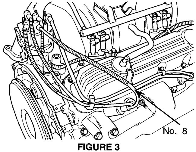
2. No.8 Cylinder Plug Wire Routing (Figure 3)
A. Remove the No.8 cylinder plug wire from the distributor cap tower terminal.
B. Remove the No.8 cylinder plug wire from the five-wire clip located at the lower rear of the valve cover.
C. Route the No.8 cylinder plug wire over the rear quarter of the right valve cover (Figure 3).
D. Position the original piece convolute from the No.8 cylinder plug wire to prevent chafing at the right valve cover and with other engine components.
E. Secure the No.8 cylinder plug wire and its convolute in place with the hose to wire clip p/n 06503441. The small end of the clip is positioned over the convolute. The large end of the clip is fastened to a heater hose (A/C line on ZJ models).
NOTE:
MAKE SURE THE NO.8 CYLINDER PLUG WIRE IS SECURE AND AWAY FROM THE COIL WIRE AND THE NO.4 CYLINDER PLUG WIRE. MAKE CERTAIN IT WILL NOT FALL DOWN AND CONTACT THE CYLINDER HEAD AND/OR EXHAUST COMPONENTS.
F. Install the No.8 cylinder plug wire to its distributor cap terminal.
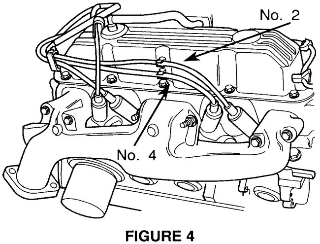
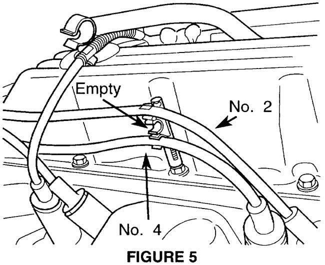
3. No.4 Cylinder Plug Wire Routing (Figure 4 and 5)
A. Remove the No.4 cylinder plug wire from the distributor cap terminal.
B. At the three-wire clip (located at the center of the lower side of the right valve cover), keep the two wires from crossing and chafing each other. Position the No.2 cylinder plug wire in the top wire slot and the No.4 cylinder plug wire in the bottom wire slot. Leave the middle wire slot empty (Figure 5).
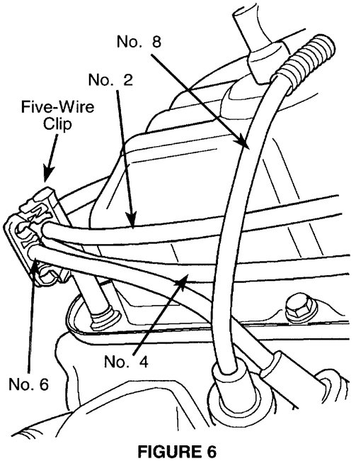
C. At the five-wire clip (located at the right rear lower side of the valve cover), keep the plug wires from crossing and chafing each other. Position the No.4 cylinder plug wire in a slot that will obtain the maximum amount of distance allowable from the No.8 cylinder plug wire (Figure 6). Remove any slack in the No.4 cylinder plug wire between the three-wire and the five-wire clips.
NOTE:
EARLIER MODEL FIVE-WIRE CLIPS LOOK SLIGHTLY DIFFERENT BUT THE SAME WIRING LAYOUT APPLIES.
D. Route the No.4 cylinder plug wire behind the transmission dipstick tube and heater hoses. On ZJ models this may not be possible due to the location of the bulkhead.
NOTE:
MAKE SURE THAT THE NO.4 CYLINDER PLUG WIRE IS, AT LEAST ONE INCH AWAY FROM THE NO.8 CYLINDER PLUG WIRE.
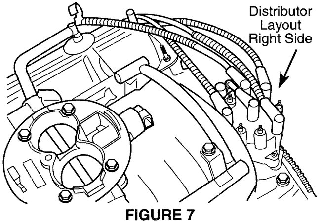
E. Install the No.4 cylinder plug wire to its distributor cap terminal (Figure 7).
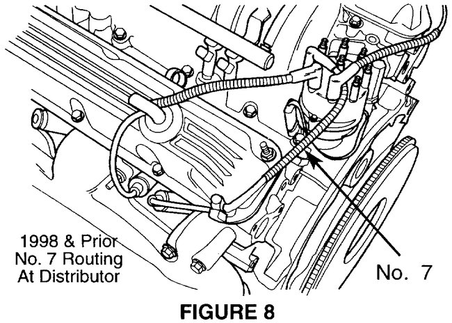
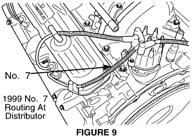
4. No.7 Cylinder Plug Wire Routing (Figure 8 and 9)
A. Verify that the No.7 cylinder plug wire crosses over the distributor cap and leaves the distributor cap between the No.3 and the No.6 tower terminals (Figure 8). This is the original wire routing for 1998 and prior model years.
B. For 1999 M.Y. Vehicles the No.7 cylinder plug wire was shortened. Reroute the No.7 cylinder plug wire so that it crosses the distributor cap and leaves the distributor cap between the No.6 and the No.5 tower terminals (Figure 9).
NOTE:
MAKE SURE THE NO.7 CYLINDER PLUG WIRE IS, AT LEAST ONE INCH, AWAY FROM THE NO.5 CYLINDER PLUG WIRE.
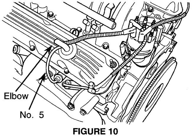
5. No. 5 Cylinder Plug Wire Routing (Figure 10)
A. Remove the No.5 cylinder plug wire from its distributor cap terminal.
B. Remove the No.5 cylinder plug wire from the five-wire clip located at the lower rear of the left valve cover.
C. Route the No.5 cylinder plug wire over the left valve cover and in front of the breather tube elbow.
D. Position the original convolute from the No.5 cylinder plug wire to prevent chafing against the valve cover and any engine components. Secure the small end of the hose to wire clip p/n 06503441 over the convolute. Secure the large end of the hose to wire clip to the breather hose.
NOTE:
MAKE SURE THE NO.5 CYLINDER PLUG WIRE IS SECURE AND AWAY FROM THE NO.7 CYLINDER PLUG WIRE. MAKE CERTAIN IT WILL NOT FALL DOWN AND CONTACT THE CYLINDER HEAD AND/OR EXHAUST COMPONENTS.
_____________________________________
It is a TSB, so there had to be issues. Let me know if this helps or if you have other questions.
Take care,
Joe
Images (Click to make bigger)
Thursday, September 20th, 2018 AT 6:30 PM
