NEUTRAL/START SWITCH
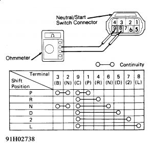
Use an ohmmeter to check continuity between neutral/start switch terminals. See Fig. If continuity is not as specified, replace switch

STARTER RELAY TEST
NOTE:Starter relays are part of the theft deterrent system. When the theft deterrent system is activated, a contact inside the theft deterrent ECU is opened. This creates an open circuit on the ground side of the starter relay, thus making the starter inoperative. Use steps 3) and 4) of starter relay testing procedure to check theft deterrent system starter cut-out (if necessary). Unlock driver's door with key to cancel starter cut-out BEFORE checking starter relay circuit.
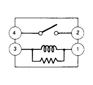
Locate and remove starter relay from fuse/relay block. Ensure continuity exists between terminals No. 1 and No. 3. Refer to Fig .

No continuity should exist between terminals No. 2 and No. 4. If continuity is not as specified, replace relay.
Apply battery voltage across terminals No. 1 and No. 3. Continuity should exist between terminals No. 2 and No. 4. If continuity is not as specified, replace relay.
Remove 3 screws and driver's side trim panel. Remove left instrument panel and key cylinder pad sub-assemblies. Remove bracket finish panel. Remove left register heater duct. Remove fuse/relay/junction block set bolts and clamp.
Separate the tilt and telescopic ECU from fuse/relay/junction block. Remove wiring harness clamp. Pull fuse/relay/junction block down. Locate theft deterrent ECU above fuse/relay/junction block (under left side of instrument cluster).
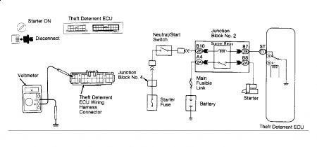
Disconnect theft deterrent ECU connectors. See Fig . Turn ignition switch to ST (start) position. With transmission in Neutral, check voltage between ST terminal of theft deterrent ECU wiring harness connector and body ground.
If voltage does not exist, check and repair harness/connections between starter relay and theft deterrent ECU. If voltage exists, and starter relay circuit is still inoperative, test and replace theft deterrent ECU

Monday, May 11th, 2009 AT 9:47 PM


