21= sunload sensor
42= air inlet servomotor circuit.
A/C-HEATER SYSTEM -1998 Lexus ES 300
NOTE: If testing is done in a dark area, Code 21 may occur even though system is normal. Shine a light at solar sensor and recheck for Code 21.
CODE 21: SOLAR SENSOR CIRCUIT
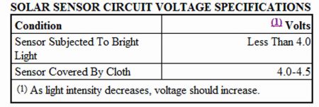
1.Remove A/C control assembly, leaving harness connectors connected. See A/C CONTROL ASSEMBLY under REMOVAL & INSTALLATION. Turn ignition on. Backprobe terminals A14-11 (Blue wire) and A15-5 (White wire) at A/C control assembly harness connector. See Fig. 5 . Measure sensor voltage. See SOLAR SENSOR CIRCUIT VOLTAGE SPECIFICATIONS table.
SOLAR SENSOR CIRCUIT VOLTAGE SPECIFICATIONS Condition (1) Volts Sensor Subjected To Bright Light Sensor Covered By Cloth 4.0-4.5 Less Than 4.0
(1) As light intensity decreases, voltage should increase.
2.If voltage is not as specified, test solar sensor. See SOLAR SENSOR under TESTING. If sensor is okay, go to next step. Replace sensor if it is defective. 3.Inspect wiring harness and connectors between sensor and A/C control assembly. Repair as necessary. If wiring harness and connectors are okay, temporarily substitute known-good A/C control assembly. Retest system.
A/C-HEATER SYSTEM -1998 Lexus ES 300
CODE 42: AIR INLET SERVOMOTOR CIRCUIT
Actuator Check
1.Remove glove box. Perform RETRIEVING CODES . After system enters self-diagnostic mode, perform ACTUATOR CHECK.
2.Press DEF button to enter step mode and display codes. See AIR INLET DAMPER AIRFLOW table. Air inlet damper operation should be as specified.
AIR INLET DAMPER AIRFLOW Code Door Position 0-2 Fresh Air 3 Fresh/Recirculated Air 4-9 Recirculated Air
3.If air inlet damper functions as specified, circuit is okay. If air inlet damper does not function as specified, test air inlet servomotor. See AIR INLET SERVOMOTOR
FUNCTIONAL CHECK.
Air Inlet Servomotor Functional Check
1.Remove air inlet servomotor. Unplug air inlet servomotor connector.
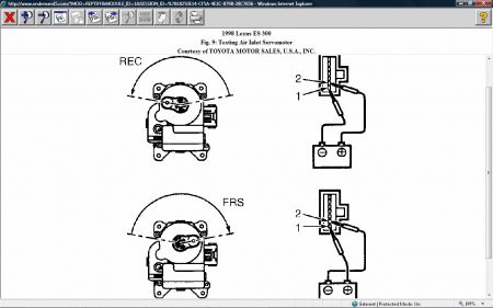
2.Connect battery voltage to air inlet servomotor connector terminal No. 2 (Red wire). See Fig. 9 . Connect terminal No. 1 (Blue/Yellow wire) to ground. Air inlet servomotor lever should move to recirculated air (REC) position. Transpose battery and ground leads. Air inlet servomotor lever should move to fresh air (FRS) position.
3.Replace air inlet servomotor if it does not operate as specified. If servomotor operates correctly, inspect wiring harness and connectors between servomotor and A/C control assembly. Repair as necessary. If wiring harness and connectors are okay, substitute known-good A/C control assembly. Retest system.
Fig. 9: Testing Air Inlet Servomotor


Saturday, August 23rd, 2008 AT 5:11 PM


