DTC P0446: EVAP EMISSION CONTROL SYSTEM VENT CONTROL MALFUNCTION
NOTE:Before performing any diagnostic test, refer toWARNINGS, CAUTIONS and NOTES under DIAGNOSTIC TESTS .
NOTE:Testing individual components does not isolate shorts or opens. Perform all voltage tests using a Digital Volt-Ohmmeter Meter (DVOM) with a minimum 10-megohm input impedance, unless stated otherwise in test procedure. Use ohmmeter to isolate wiring harness shorts or opens.
Diagnostic Aids
Malfunction code is set when solenoid coil surge voltage (system voltage +2) is not detected when EVAP emission vent solenoid is turned on/off. Check for following possible problems:
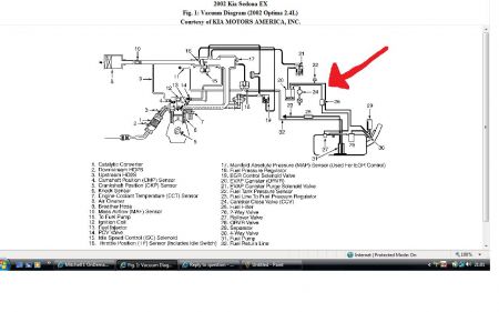
Open or short between Main relay and Canister Control Valve (CCV).
Open or short between CCV and Engine Control Module (ECM).
Faulty CCV.
Test Procedure
Turn ignition off. Thoroughly check CCV harness connector terminal for loose, bent, corroded, contaminated, deteriorated or damaged connector terminals. If connector terminals are okay, go to next step. If connector and terminals are faulty, repair or replace as necessary and go to step 7 .
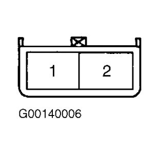
Disconnect CCV 2-pin harness connector. Measure resistance between CCV connector terminal No. 1 and 2 (component side). Resistance should be 23-26 ohms at 68 °F (20 °C). If resistance is as specified, go to next step. If resistance is not as specified, temporarily install a known-good PCSV and check for proper operation. If problem is corrected, replace valve and go to step 7 .
With CCV 2-pin harness connector disconnected. See Fig. 21 . Turn ignition on. Measure voltage between ground and CCV harness connector terminal No. 1 (Brown wire). Voltage should be battery voltage. If voltage is as specified, go to step 7 . If voltage is not as specified, go to next step.
Turn ignition off. Locate fuses and Main relay in engine compartment fuse/relay box. Check Main relay operation and fuses condition. For Main relay operation test, see FUEL PUMP & MAIN RELAYS (SEDONA) under RELAYS & SOLENOIDS in SYSTEM & COMPONENT TESTING article. Also if necessary check Main relay circuits. See WIRING DIAGRAMS article. If fuses, relay and circuits are okay, go to next step. If fuses, relay or circuits are faulty, repair or replace as necessary, and go to step 7 .
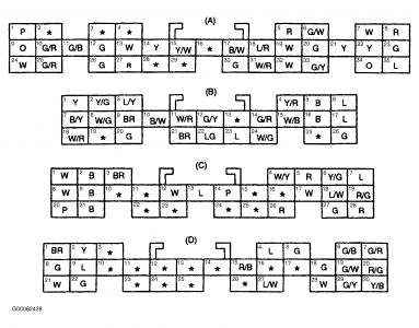
Disconnect ECM harness connector "A". See Fig. 4 . Measure resistance between CCV connector terminal No. 2 (White wire) ECM connector terminals A24. Resistance should be below one ohm. If resistance is as specified, go to next step. If resistance is not as specified, repair open circuit as necessary and go to step 7 .
With CCV and ECM harness connectors disconnected. Measure resistance between ground and CCV harness connector terminals No. 2 (White wire). Resistance should be infinite. If resistance is as specified, temporarily install a Known-good CCV and check for proper operation. If problem is corrected, replace CCV and go to next step. If resistance is not as specified, repair short circuit as necessary and go to next step.
After repair, return vehicle to original condition. Clear codes using Hi-Scan Pro/Kia Data Pro Scan tool or equivalent. Verify repairs by driving vehicle and monitoring for pending codes. If DTC is set during test drive, follow appropriate DTC test procedure.
Fig. 21: Identifying Canister Control Valve Connector Terminals


Wednesday, March 4th, 2009 AT 8:03 PM


