Hello, we hope this helps.
COOLANT TEMPERATURE SENSOR AND CIRCUIT - DTC 14
The ECM looks for the coolant temperature sensor signal voltage out of range.
The coolant temperature sensor is a negative temperature coefficient sensor; the higher the temperature, the lower the resistance. The sensor is located on top of the thermostat housing
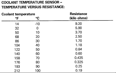
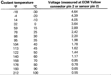
The coolant temperature sensor signal is used by the ECM for the control of a number of functions:
- Cranking enrichment
- Warm-up enrichment
- Acceleration enrichment
- Air injection
- Idle speed control
- Exhaust gas recirculation
- Evaporative canister purge
The signal voltage is monitored three ways:
Coolant temperature rise after engine cold start.
Coolant temperature decrease during engine normal temperature operation.
Signal voltage outside the normal coolant temperature sensor operating range.
Conditions Required For DTC 14 Flagging:
After cold start Engine condition: After start warm-up Coolant temp. sensor voltage signal to ECM: 3.53 volts or less Response time: 6 minutes
Normal operating temperature Engine condition: Normal operating temperature Coolant temp. sensor voltage signal to ECM: Voltage decrease of 0.7 volt or greater Response time: 196 milliseconds
Normai coolant temperature sensor operating range Coolant temp. sensor voltage signal to ECM: Less than 0.1 volt or greater than 4.9 volts Conditions monitored: Any time during ignition ON Response time: 64 milliseconds
Limp Home Default
If DTC 14 is flagged, the warm-up strategy defaults to a trim value of 26 °C (80 °F) . Start and after-start values are used that allow the engine to be started over a wide temperature range.
Possible Faults
- High resistance connection at coolant temperature sensor or ECM
- High resistance or open circuit wiring from the ECM to the coolant temperature sensor
- Short circuit wiring from the ECM to the coolant temperature sensor
- High resistance in ECM ground circuit
- Defective engine coolant thermostat
- Defective coolant temperature sensor
Diagnostic Notes
The coolant temperature signal voltage can be monitored and intermittent faults captured using the PDU "Datalogger" function.
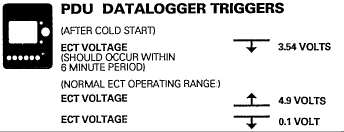
If DTC 11, 12, 16, 18, 19 and/or 39 are also flagged, suspect a defective sensor ground circuit to the ECM (BY wire) or defective ECM ground circuit to the front bulkhead ground stud.
Circuit Diagram
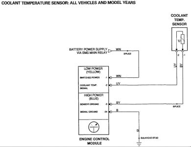
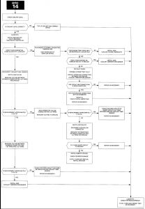
Flow Chart: DTC 14
Friday, October 17th, 2008 AT 11:04 PM


