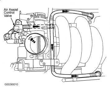
Chack for vacuum leaks around throttle body/AAI ..the P0065 code could be the reason for the 420/430 codes but Check for damage to the catalytic convertors, also check the wiring to the sensors !
P0420Catalyst Efficiency Below Threshold (Right Bank)
P0430Catalyst Efficiency Below Threshold (Left Bank)
DTC P0065: AIR ASSISTED FUEL INJECTION CONTROL RANGE/PERFORMANCE (V8 MODELS)
NOTE:Limited information available from manufacturer.
NOTE:For circuit reference, see appropriate diagram in WIRING DIAGRAMS article.
System Description
Air Assisted Injection (AAI) is fitted to the 4.0L naturally aspirated engine to improve the atomization of the fuel spray pattern when cold, providing the following benefits:
Reduce Hydrocarbon (HC) emissions produced by combustion.
Improved combustion stability when cold, by allowing the use of increased ignition retardation for faster catalyst warm up, for additional HC reduction.
The system uses manifold vacuum, under cold start/part throttle conditions, to draw air through a modified injector nozzle, producing a jet which mixes with the fuel spray to increase atomization. At higher engine loads, the vacuum is insufficient to have this effect. The injector air assistance supply is controlled by the engine management system.
Operation is based on the use of top (fuel) fed injectors with an air feed around the nozzle regions and therefore requires a modified induction manifold. The injectors are sealed in 2 air supply rails which are integral with the manifold. The rails are closed at both ends and are center fed by plastic hoses and a "T" piece from the Air Assist Control (AAC) valve. The 2 fuel rails are connected with a crossover pipe, that form a detachable assembly and are a push fit onto the fuel injectors that are secured by a clip. The fuel rails are then bolted to the intake manifold. See Fig. 2.
Fuel injectors are top fuel fed, solenoid controlled devices with conventional fuel delivery operation, but have a plastic shroud fitted over the nozzle end. See Fig. 3. Air from the supply rail is drawn by manifold vacuum through 4 small holes in the side of the shroud and past the fuel nozzle to exit by the 2 spray orifices in the shroud. When the fuel is injected into this airflow, an improved spray mixture with reduced droplet size is produced. An effect of AAI is to slightly increase the convergence of the 2 spray patterns as they enter the cylinder head inlet ports, producing wall wetting, which is reduced by re-profiling changes to the inlet ports.
The air supply to the injectors is controlled by the solenoid operated AAC valve which is bolted to the throttle body. The control valve receives air through an integral passage in the upper throttle body, from an entry hole in the upper throttle bore above the throttle valve. See Fig. 4.
The AAC valve is driven by a Pulse Width Modulation (PWM) signal at 5 volt amplitude and opens in a direct proportion to an increase in the duty cycle. The valve is fully open from cold until 140 °F (60 °C), when a 50 percent duty cycle is applied. At 158 °F (70 °C) the valve is fully closed (above this temperature, air assistance is not required). Note that idle speed is controlled as before by the throttle valve.
Possible Causes
Restricted, disconnected or broken Air Assisted Injection (AAI) system piping.
AAI valve failure.
Fig. 2: Identifying Air Assisted Injection (4.0L)

Sunday, March 28th, 2010 AT 6:03 AM


