Hello,
It sounds like you have an ignition coil that is out, here is a guide to help you confirm.
https://www.2carpros.com/articles/how-to-test-an-ignition-system
DTC Confirmation Test
Malfunction is detected when ECM does not receive signal from ignition primary circuit during engine
cranking or running. Possible causes are:
Ignition primary circuit open or shorted.
Defective power transistor (integral with ignition coil).
Defective condenser.
Defective Crankshaft Position (CKP) sensor (REF).
CKP sensor (REF) circuit open or shorted.
To set DTC, turn ignition on. Select DATA MONITOR with scan tool. Start engine. If engine does not
start, crank engine for at least 5 seconds.
Procedure
1. Turn ignition off and restart engine. If engine starts, go to step 8 . If engine does not start, leave
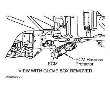
ignition on. Measure voltage between ground and ECM terminals No. 110 and 112. See Fig. 1 and
Fig. 2 . If battery voltage exists, go to next step. If battery voltage does not exist, repair power
supply circuit. See ENGINE CONTROL MODULE (ECM) under COMPUTERIZED ENGINE
CONTROLS in SYSTEM & COMPONENT TESTING article.
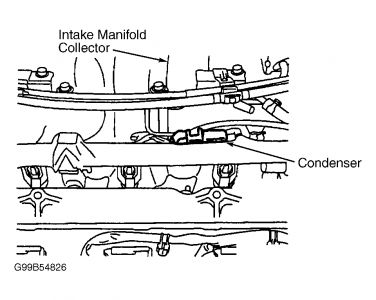
2. Turn ignition off. Disconnect condenser harness connector. See Fig. 38 . Turn ignition on.
Measure voltage between ground and condenser harness connector Red wire. If battery voltage
exists, go to step 6 . If battery voltage does not exist, go to next step.
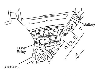
3. Turn ignition off. Disconnect ECM relay. See Fig. 39 . Check continuity of Red wire between
ECM relay harness connector terminal No. 7 and condenser harness connector. See Fig. 16 . Also
check circuit for short to ground and short to voltage. Repair as necessary and retest system. If circuit is okay, go to next step.
4. Measure voltage between ground and ECM relay harness connector terminal No. 6 (Purple wire).
If battery voltage exists, go to next step. If battery voltage does not exist, repair open or short
circuit and retest system. See WIRING DIAGRAMS article.
5. Using jumper wires, apply battery voltage and ground to ECM relay terminals No. 1 and 2. See
Fig. 16 . Check continuity between terminals No. 3 and 5. Also check continuity between
terminals No. 6 and 7. Continuity should exist. Remove jumper wires. Continuity should not exist.
If operation is as specified, go to step 12 . If operation is not as specified, replace ECM relay and
retest system.
6. Turn ignition off. Check continuity between engine ground and condenser harness connector
Black wire. Also check circuit for short to voltage. Repair as necessary and retest system. If
ground circuit is okay, go to next step.
7. Measure resistance between condenser terminals. Resistance should be more than one megohm at
77°F (25°C). If resistance is as specified, go to next step. If resistance is not as specified, replace
condenser and retest system.
8. Turn ignition off. Reconnect all harness connectors. Disconnect ignition coil harness connectors.
Turn ignition on. Measure voltage between ground and each ignition coil harness connector
terminal No. 3 (Red wire). If battery voltage exists, go to next step. If battery voltage does not
exist, repair open or short between ignition coil harness connector and ECM relay. See WIRING
DIAGRAMS article. Retest system.
9. Turn ignition off. Check continuity between engine ground and each ignition coil harness
connector terminal No. 2 (Black wire). Also check circuits for short to voltage. Repair as
necessary and retest system. If ground circuits are okay, go to next step.
10. Disconnect ECM harness connector. See Fig. 1 . Check continuity between each ignition coil
harness connector terminal No. 1 and ECM harness connector. See IGNITION COIL/ECM
CIRCUIT IDENTIFICATION table. See Fig. 2 . Also check circuits for short to ground and
short to voltage. Repair as necessary and retest system. If circuits are okay, go to next step.
11. Measure resistance between ignition coil terminals No. 2 and 3. If resistance is zero ohms, replace
ignition coil and retest system. If resistance is more than zero ohms, go to next step.
12. No problem is indicated at this time. Problem may be intermittent. See TESTING PROCEDURE
under SELF-DIAGNOSTIC SYSTEM in SELF-DIAGNOSTICS - INTRODUCTION article.
Figure 1

Figure 2

Figure 38

Figure 39

Wednesday, February 4th, 2009 AT 1:55 AM


