If you're expecting to find voltage at the ignition coil, you haven't done the test I described. The results of that test will tell us where to go next.
The Engine Computer turns the automatic shutdown, (ASD) relay on for up to two seconds when you turn the ignition switch to "run", then it turns it back off until it sees engine rotation. That is a safety system built into almost all fuel injected vehicles. If a fuel line is ruptured in a crash, the fuel pump would dump raw gas on the ground, creating a serious fire hazard. Instead, with no fuel pressure, no fuel can spray from the injectors. The engine would stall, there would be no signal pulses from the camshaft position sensor or the crankshaft position sensor. That tells the computer to turn the ASD relay off to remove power to that circuit. The 12 volts is switched off to the ignition coil(s), injectors, oxygen sensor heaters, alternator field, and the fuel pump. On some models there is a separate relay for the fuel pump, but it is switched on and off at the same time as the ASD relay.
Some older models, GMs in particular, used to use a tap on the oil pressure switch for the same purpose.
You can check for 12 volts for that first two seconds at the ignition coil if you want to, but I find it much easier and faster to back-probe through the rubber weather seal at one of the injectors. You'll find the same dark green / orange wire at all of those places. You must either use a helper or you can set the test light in a way you can see it from inside the truck when you turn the ignition switch. Some people use a voltmeter for this, but they often react too slowly to catch that brief 12-volt pulse. Also, for this type of problem, a digital voltmeter can give false results showing what appears to be 12 volts when it really isn't there.
The important point here is if you do see 12 volts for that initial two seconds, we're done in that circuit and can move on. There can't be a short to ground on that line, the relay, fuse, and that part of the circuit have to be okay, and the computer has control of the relay. Then the important next step is to see if the 12-volts comes back during cranking. If it does, we have either an ignition system problem, (about two percent of crank / no-starts), or a fuel system problem, (about three percent of crank / no-starts), but not both. By far, (about 95 percent) the most common cause of crank / no-starts is a loss of both fuel and ignition at the same time, and that involves the ASD relay not turning back on during cranking. What misleads a lot of people is due to that initial two seconds the ASD relay is on, the fuel pump has had the fuel pressure up to normal, so it looks like the fuel system is not involved in the diagnosis. In fact, the pump does not run during cranking, but pressure doesn't bleed down because the injectors aren't firing either. Too many people get hung up on the loss of spark and fail to look for what else isn't working.
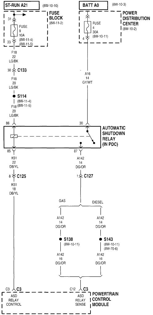
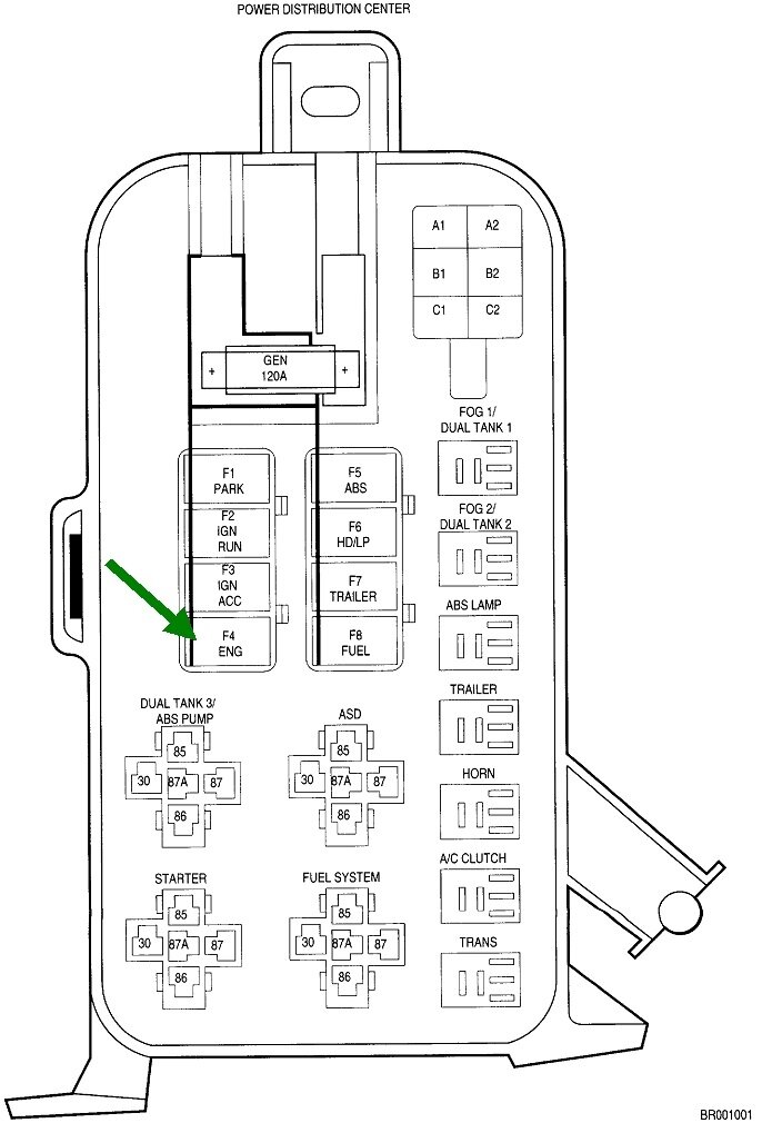
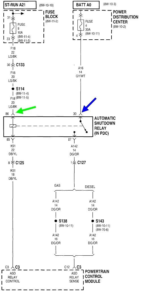
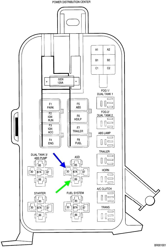
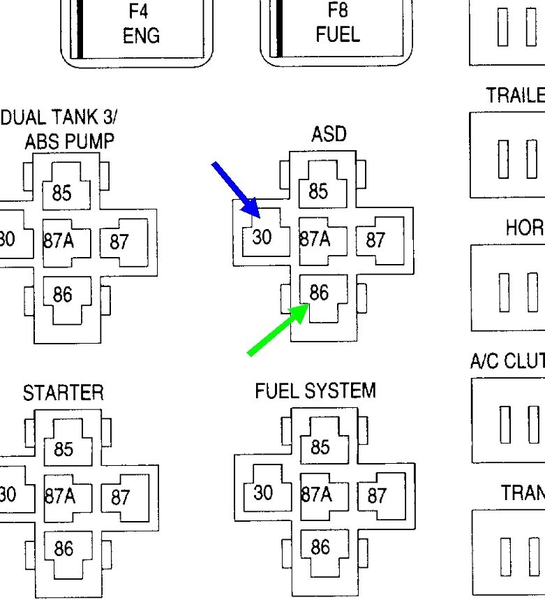
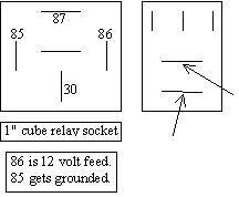
To back up a step, if you do indeed find no 12 volts at any time on the dark green / orange wire, we have to look at the ASD relay circuit. Either it isn't turning on or the switched 12 volts is being lost. Remove the ASD relay, then in its socket, check for 12 volts on terminal # 30. It should be there all the time. Just touch the probe of the test light, (or voltmeter) to the terminal. Don't poke the probe into the terminal as that can spread it leading to intermittent problems in the future. Terminal # 30 is shown with the blue arrow in the second drawing. These can be hard to read, so I blew it up for you in the third drawing. The fourth drawing is just the same thing in generic form for all the different relay styles. The one in the upper left corner pertains to your truck. I'll come back to terminal # 30 in a minute.
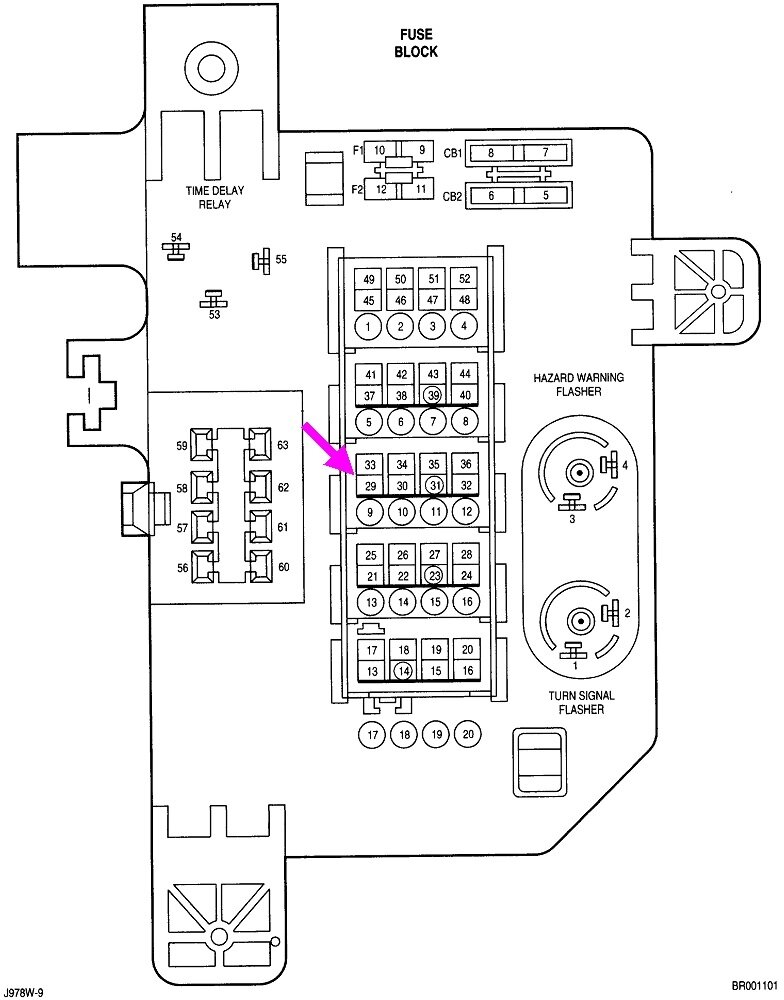
If you do have 12 volts on terminal # 30, check next on terminal # 86. That one should have 12 volts when the ignition switch is in "run". If that's missing, check fuse # 9, a 10-amp, but he is in the Junction Box, (inside fuse box), purple arrow in the fourth drawing. That box is on the left side of the dash, (fifth drawing).
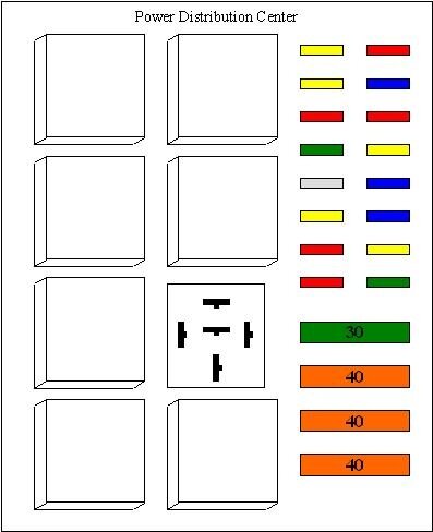
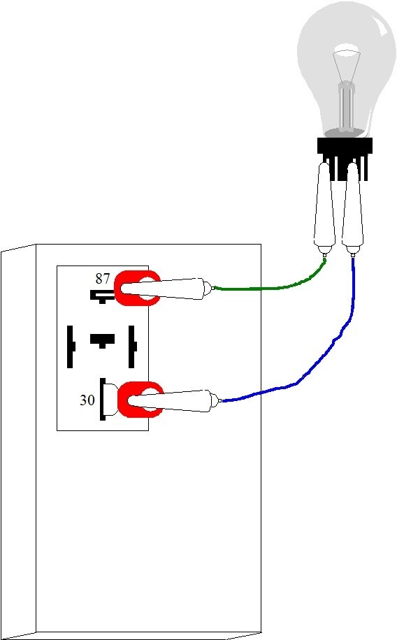
If there's 0 volts on terminal # 30, fuse # 4 is blown. It will have to be replaced for the next test, but first, use your ohm meter to check for real low resistance to ground on terminal # 87. You can use a paint-free metal point on the body or on the engine for ground. If you find close to 0 ohms, the new fuse is going to blow when you reinstall the ASD relay and turn on the ignition switch. Instead, leave the relay out, then we will bypass it with a light bulb. A 3157 brake light bulb works well for this procedure. To simplify this for the benefit of others researching this topic, I put together a series of drawings to show what we're about to do. The bulb will limit current to a safe one amp, and it will give a visual indication when the short is present. When it is, the bulb will be full, normal brightness, and hot, so be careful that it isn't in contact with anything that will melt or burn. When you do something to remove the short, the bulb will get dim or go out. At that point the circuit will resume trying to work, but the bulb will likely limit current too much. You can wiggle wire harnesses and unplug things to see what makes the short go away. Look for harnesses that fell down and are laying on hot exhaust parts or on top of metal brackets with sharp edges. Also look for a fat harness laying on the inner fender. Those can slide back and forth as the engine rocks, leading to worn paint and wire insulation, then an intermittent short.
This light bulb procedure can be done by replacing a fuse or a relay. Starting with the sixth drawing, I showed the steps for bypassing the relay because that allows you to safely power up the circuit without needing to turn on the ignition switch. Also, in this circuit, if you replaced the fuse with the test bulb, you would need the computer to turn the relay on. That's a miserable job unless you have a scanner to do that.
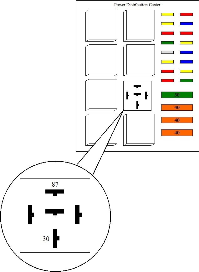
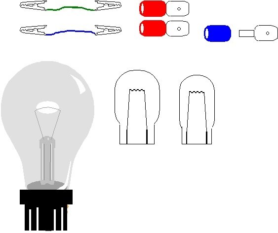
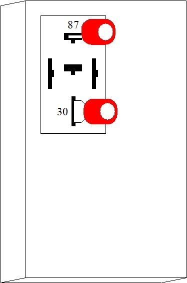
Drawing # 7 just shows an expanded view of a common, typical relay socket. # 8 shows the items needed. Two small jumper wires with clips on the ends. A dozen cost around $4.00 at Harbor Freight Tools. I use the small ones because the alligator clips fit into most things being tested. The size of light bulb depends on the type of circuit being diagnosed. A common 3157 brake light bulb will allow a maximum of one amp of current to flow. The smaller 194 "peanut" bulb allows up to a half amp. If you need more current, such as when working in a heater fan motor circuit, a common 9004 head lamp bulb will allow five amps with the low beam and around six amps if using the high beam filament. You'll need two generic flat spade-type universal crimp-style terminals. A small box of them costs only a couple of bucks at any hardware store. These are the same thickness as a relay's terminals, so they won't spread or stretch the terminals in the socket.
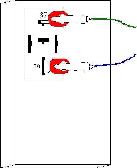
Starting in drawing # 9, the universal terminals are plugged into relay terminals # 30 and 87. (They form the letter "T"). Next, the clip leads are attached, and finally, they're clipped to the bulb. At this point if there's a short present, the bulb will be lit up full brightness. The new fuse won't blow because only one amp of current is flowing. Start by shifting wire harnesses around and unplugging things to see when the short goes away. When it does, the bulb will get dim of go out. You might unplug the oxygen sensors to see if one has a heating element that has become grounded inside. A deformed rear cover on the alternator could touch the 12-volt supply terminal. A shorted injector or ignition coil is pretty much unheard of, and won't show up with the test bulb because none of those circuits are being turned on on their ground sides by the computer. If the short is related to those things, the better suspect is a grounded wire going to one of them.
Once you find and repair what is shorted, reinstall the ASD relay and the engine should start and run.
Remember, this all has to do with never finding 12 volts on the dark green / orange wire. If you do see 12 volts for the initial two seconds, we have a totally different problem. Start by reading and recording any diagnostic fault codes. Chrysler made doing that yourself much easier than any other manufacturer. Cycle the ignition switch from "off" to "run" three times within five seconds without cranking the engine. Leave it in "run", then watch the code numbers appear in the odometer display. You can go here:
https://www.2carpros.com/trouble_codes/obd2
to see the definitions, or I can interpret them for you. There's three important points to be aware of with these codes. First, they never ever say to replace a part or that one is bad. They only indicate the circuit or system that needs further diagnosis, or the unacceptable operating condition. Second, many people falsely believe the Check Engine light must be on for there to be a fault code set. In fact, there's over 2,000 potential codes. Only about half of them pertain to things that could adversely affect emissions. Those are the codes that turn on the Check Engine light. In this case we're hoping or expecting to find codes related to the crankshaft position sensor or the camshaft position sensor. Those codes may not turn on the Check Engine light because the engine can't run with a failed sensor, so it can't pollute.
The third point is it is fairly common to have a failed cam or crank sensor but no fault code, so for that reason, don't assume a sensor is good just because no code is set. The Engine Computer needs some time to detect a defective sensor, as in when a stalling engine is coasting to a stop. Simply cranking the engine may not be enough for a code to set. This is where we need a scanner to view live data. I use Chrysler's DRB3 for all of my vehicles. It lists both sensors with a "No" or "Present" during cranking to show if the signal pulses are showing up. When both signals are there is when the computer turns on the ASD relay.
Avoid disconnecting the battery or running it dead before the fault codes are read. Doing so erases the codes, then that valuable information is lost.
You mentioned the truck has been sitting for some time. Is that because this problem developed, or did the problem develop while it was sitting? If it occurred while it was sitting, bad gas and mouse-chewed wires are better suspects than a failed part.
To answer your original question about the ignition coil, once the engine is running and the ASD relay is switched on, you'll find steady 12 volts on the positive terminal. Measuring on the negative terminal is not a valid test and it has no meaning. With a test light, you'll see it is not as bright as on the positive terminal. If you were to use an oscilloscope to watch the voltage, you'd see it sitting at around one or two volts most of the time, then it would pop up to 12 volts briefly. The Engine Computer grounds the negative terminal, then current flow causes a huge electromagnetic field to build up inside the coil. Based on the timing pulses from the cam and crank sensors, the computer removes, or switches off that ground forcing current to go instantly to "0". The resulting big voltage spike created in the primary gets multiplied in the secondary to create the spark voltage. Old analog voltmeters with a pointer would show the lower average voltage on the negative terminal. Digital meters would have a nervous breakdown trying to do that. They take a reading, analyze it, then display it while taking the next reading. One reading might be taken when there's 12 volts there, and the next reading might see one volt. The display would bounce around way too much to be of any use.
I know this is a lot, but hopefully this will get us pointed in the right direction. Let me know how you make out up to this point.
Images (Click to make bigger)
Tuesday, November 8th, 2022 AT 2:27 PM
