IGNITION SWITCH/COLUMN LOCK ASSEMBLY
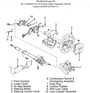
1.Disconnect negative battery cable. Remove horn pad and steering wheel. Remove lower instrument panel and steering column shrouds. See Fig. 4 . Disconnect both ignition switch and combination switch wiring connectors located behind lower instrument panel. Remove tie-straps retaining harnesses to column.

2.Remove combination switch retaining bolts, and slide switch from shaft. Remove snap ring and bushing from in front of ignition switch. Turn ignition switch to ON position to unlock column.
3.Remove ignition switch/column lock assembly retaining bolts from rear of switch assembly. To access switch assembly retaining bolts, it may be necessary to remove upper column bracket bolts from instrument panel in order to lower steering column. Slide switch assembly from shaft.
4.To install, reverse removal procedure. Ensure proper operation of steering lock and ignition switch mechanism before completing reassembly of column components. Tighten all bolts to specification.
Note : If equipped with SRS, be careful not to turn the steering after removal of the steering wheel and note the spring reel position, DO NOT turn it in any direction and keep the marking as it is.
SPONSORED LINKS
Saturday, August 7th, 2010 AT 9:16 AM
