The CYP is in the distributor and it is possibly a fault with it or its wiring circuit. A loose connection maybe.
Here are the diagnostic procedures.
DTC P1381 & P1382: CYP SENSOR
NOTE:
DTC P1381 indicates intermittent interruption in Cylinder Position (CYP) sensor circuit. DTC P1382 indicates no signal in CYP sensor circuit.
1. Perform PCM reset procedure. Start engine. If DTCs P1381 and/or P1382 are present, go to next step. If DTCs P1381 and/or P1382 are not present, problem is intermittent, system is okay at this time. Check for poor connections or loose wires at 14-pin connector (located at right shock tower), CYP
connector and PCM.
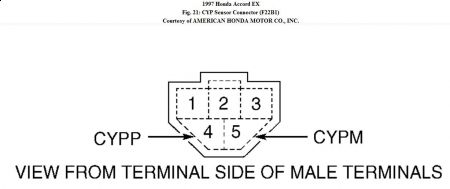
2. Turn ignition off. Disconnect distributor 4-pin (F22B2) or 5-pin (F22B1) connector. On F22B1, measure resistance between sensor terminal No. 4 (CYPP) and terminal No. 5 (CYPM). See Fig. 21
. On F22B2, measure resistance between sensor terminal No. 2 (CYPP) and terminal No. 4 (CYPM). See Fig. 22. If resistance is 800-1500 ohms, go to
next step. If resistance is not as specified, replace distributor ignition housing.
3. Check for continuity between ground and CYP sensor terminal No. 2 and terminal No. 4 (F22B1) or terminal No. 4 and terminal No. 5 (F22B2), individually. See Fig. 21 or Fig. 22. If continuity does not exist, go to next step. If continuity exists, replace distributor ignition housing.
4. Reconnect distributor 4-pin or 5-pin connector. Disconnect PCM 31-pin connector "C". See Fig. 3. Measure resistance between PCM connector terminal C4 and terminal C14. If resistance is 800-1500 ohms, go to next step. If resistance is not as specified, repair open in suspect wire(s) between distributor and PCM.
5. Check for continuity between ground and PCM 31-pin connector "C" terminal C4. If continuity exists, repair short in wire between distributor and PCM. If continuity does not exist, substitute a known-good PCM and recheck. If symptom or problem goes away, replace original PCM.


Friday, January 29th, 2010 AT 1:09 PM


