Top brake light is not working

1996 GMC SIERRA
246,000 MILES • 4.3L • 6 CYL • 4WD • MANUAL
Avatar
BABYJAY531
  • MEMBER
  • 89 POSTS
Something is not right with the wiring for these connectors. every time I hit the brake my tail lights the bulbs come on the middle set but not the top. I am stuck.
Sep 13, 2017 at 4:11 PM
Advertisement
Avatar
CJ MEDEVAC
  • CERTIFIED EXPERT
  • 11,004 POSTS
Check the grounds.

Sometimes if the ground is not really grounding, the electricity will seek out a ground of some sort, such as the other wires going through the bulbs.

You may want to use a temporary jumper (alligator clip ends).

Hook to the body and to the wire/metal/fixture for the bulbs ground.

Give it a test,

this may verify whether you need to find and reconnect the original ground/remove and clean corrosion or paint where it meets the car body.

Keep us posted,

We still may be able to aid further.

The Medic
Sep 13, 2017 at 5:59 PM
Avatar
BABYJAY531
  • MEMBER
  • 89 POSTS
Do you have any pictures that show where the wires go?
Sep 14, 2017 at 7:04 AM
Advertisement
Avatar
CJ MEDEVAC
  • CERTIFIED EXPERT
  • 11,004 POSTS
Am I good or what!

Went into "Prodemand"

Found the correct diagram using your information.

This is the "exterior lamps" wire diagram.

In order to get this I had to make three screenshots, take them to Ms Paint to crop them out.

Here is the deal, I insured they all overlapped. Diagram one is the top, diagram two is the middle, diagram three is the bottom.

If you print them, you can slide them together until they overlap/ sync, then tape them.

Click on them below

Return bearing good news!

The Medic
Sep 14, 2017 at 4:24 PM
Avatar
BABYJAY531
  • MEMBER
  • 89 POSTS
I found a wire that was smoking it says allum fine number is 14 and the wire is gray do u got a wiring diagram
Sep 20, 2017 at 6:46 PM
Avatar
BABYJAY531
  • MEMBER
  • 89 POSTS
Fuse
Sep 20, 2017 at 6:46 PM
Avatar
CJ MEDEVAC
  • CERTIFIED EXPERT
  • 11,004 POSTS
Any idea what the fuse/ wire controlled so that I might find the system it's in?

Many diagrams for these new vehicles, sorted by system, such as AC/ Exterior lights/ etc./ etc.

The Medic
Sep 20, 2017 at 7:03 PM
Avatar
BABYJAY531
  • MEMBER
  • 89 POSTS
When I made connections the wires I sent u a plug that I connect I traced it but there are 3 wires of the same color that is spliced with 3
Sep 20, 2017 at 9:10 PM
Avatar
BABYJAY531
  • MEMBER
  • 89 POSTS
Do u got the harness diagram for the connectors in the pic above
Sep 24, 2017 at 10:53 PM
Avatar
BABYJAY531
  • MEMBER
  • 89 POSTS
You there
Sep 26, 2017 at 7:52 AM
Avatar
CJ MEDEVAC
  • CERTIFIED EXPERT
  • 11,004 POSTS
Here!

Lots and lots of diagrams. Way too many for me to copy (screenshot) and send them all!

Narrow it down to what system they are in, I'll try to get the diagram.

The Medic
Sep 26, 2017 at 6:06 PM
Avatar
BABYJAY531
  • MEMBER
  • 89 POSTS
1 gray goes to heater 1 goes to the cargo light 1 goes to the instrument cluster wires
Sep 27, 2017 at 12:43 PM
Avatar
CJ MEDEVAC
  • CERTIFIED EXPERT
  • 11,004 POSTS
Kinda busy tonight with the wifey.

Takes a while to screenshot stuff and process it thru M.S Paint in order to post it so that it is big enough to read. Beings that they are from "Prodemand", I cannot just copy and paste them.

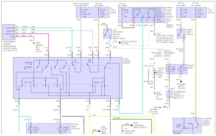
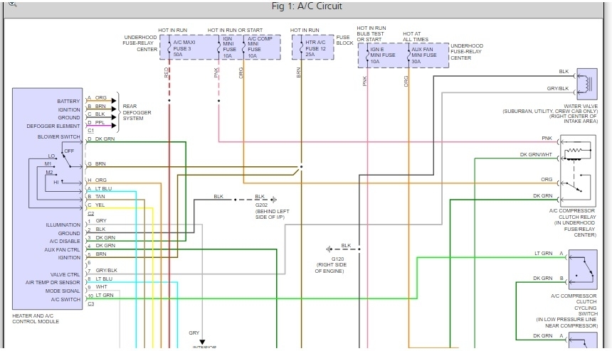
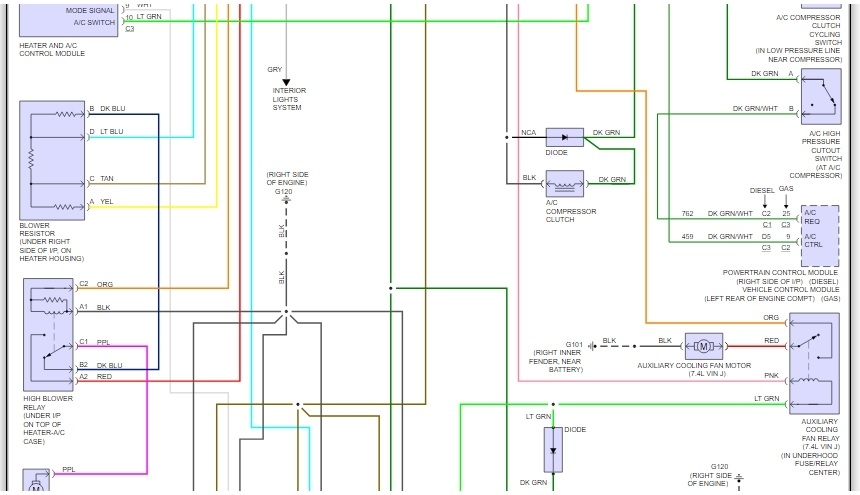
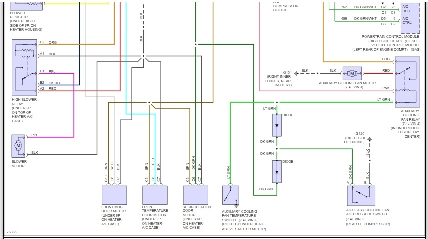
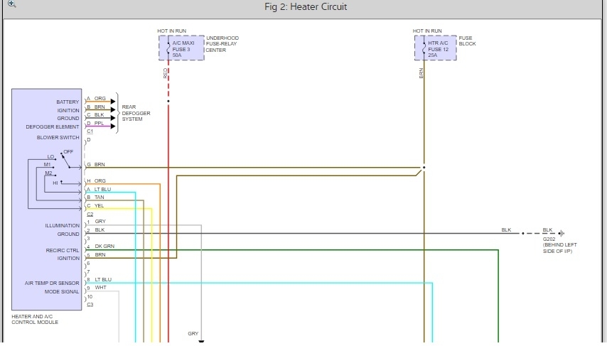
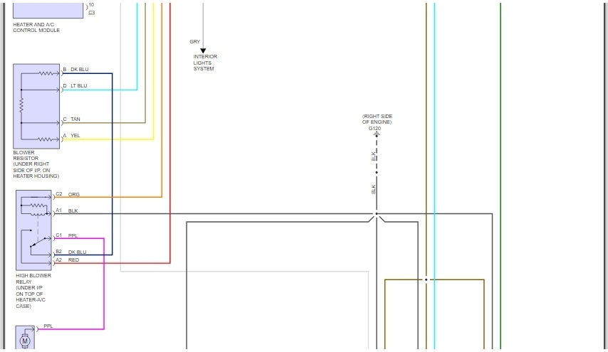
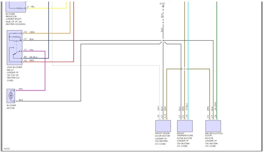
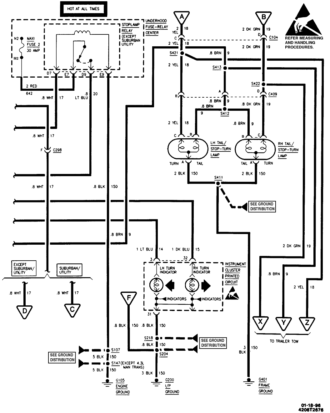
So far I have gotten you the "A/C" and "Heater" diagrams ('cause maybe the wire you described might go to either of the system)

I'll work on the others tomorrow

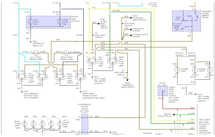
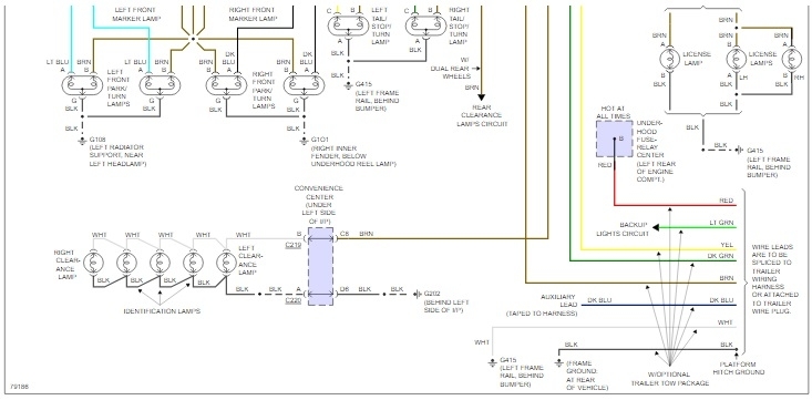
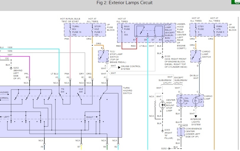
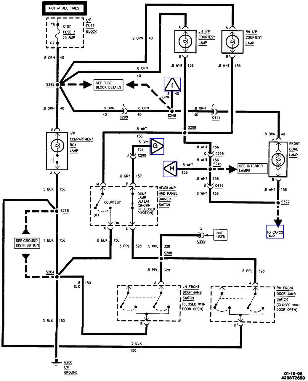
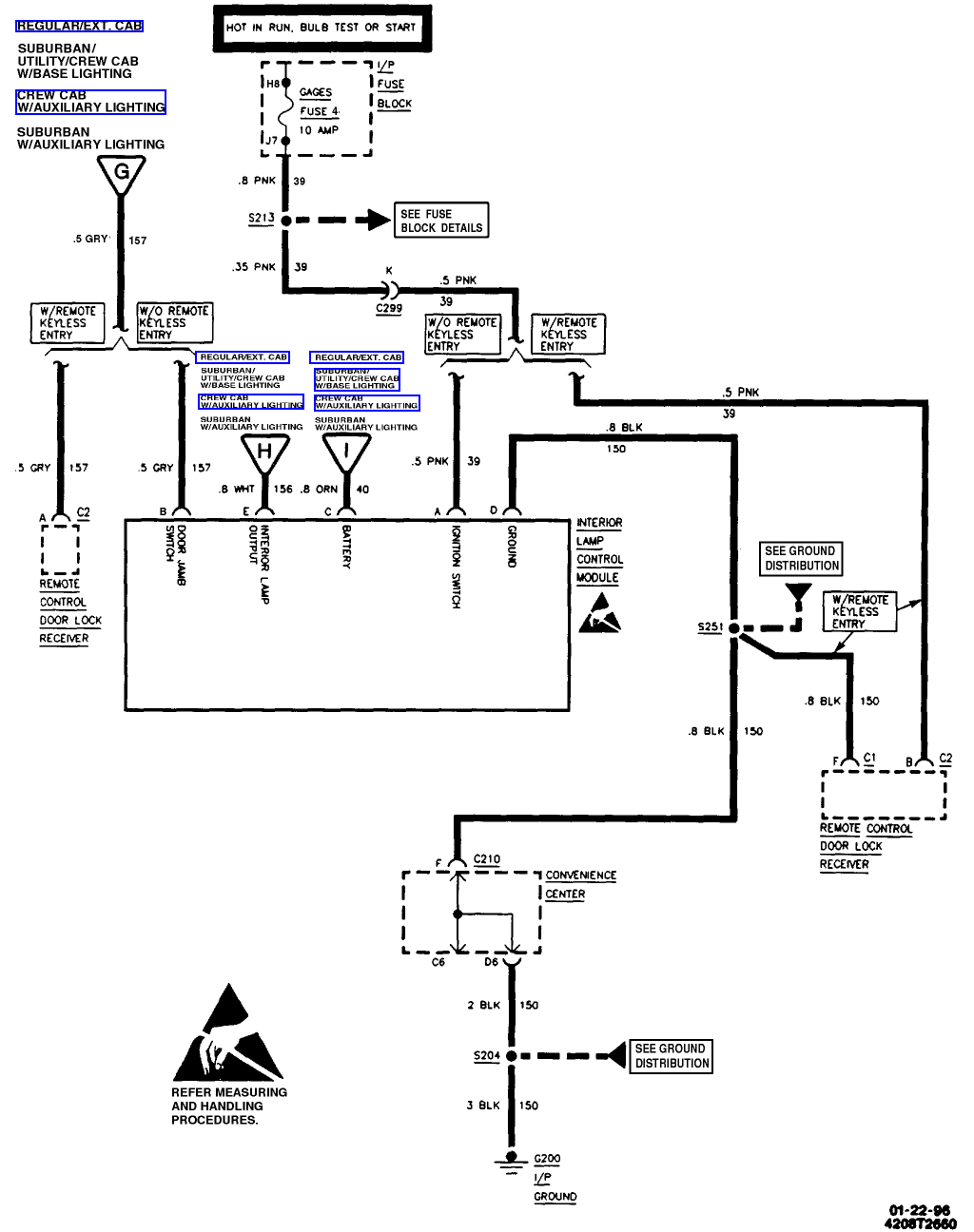
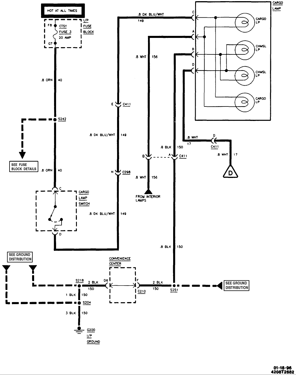
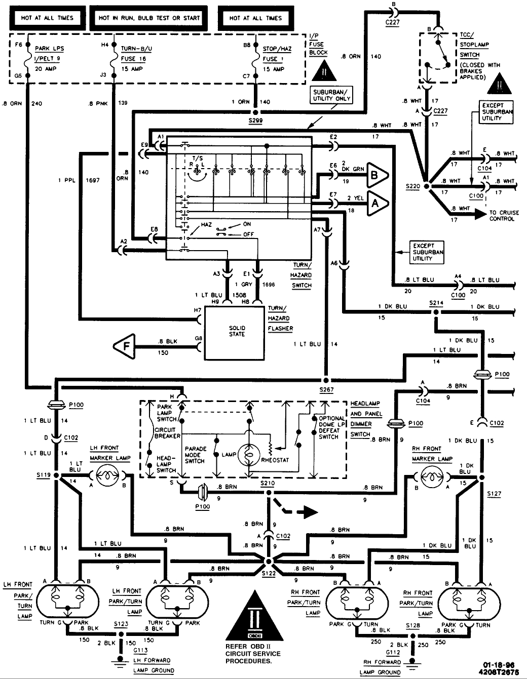
Right now (below) are six shots.

1st three are "A/C" (of one diagram)

2nd three are "Heater" (of one diagram)

They overlap so no info is missing (if printed, they would slide over each other). 1st three stack on each other, so do the 2nd three (two separate diagrams)

Let me know if these do anything for you, I'll attempt the others tomorrow.

The Medic

Sep 27, 2017 at 7:46 PM
Avatar
BABYJAY531
  • MEMBER
  • 89 POSTS
I will look tomorrow I will trace them wires again to make sure
Sep 27, 2017 at 7:59 PM
Avatar
STRAILER
  • CERTIFIED EXPERT
  • 53,855 POSTS
Please let us know what happens.

Cheers, Ken
Sep 28, 2017 at 2:14 PM
Avatar
BABYJAY531
  • MEMBER
  • 89 POSTS
I double checked them wires and 1 goes to heater 1 goes to the cargo light and 1 goes to the instrument cluster wires
Sep 28, 2017 at 6:52 PM
Avatar
CJ MEDEVAC
  • CERTIFIED EXPERT
  • 11,004 POSTS
Diagram 1) exterior lights/ partial diagram/ shows whole cargo light circuit sorta top/ mid right.

Diagrams 2-4) Instrument cluster/ full diagram in 3 screenshots (they overlap). 1st is top/ 2nd is middle/ 3rd is bottom.

The Medic
Sep 29, 2017 at 7:05 PM
Avatar
BABYJAY531
  • MEMBER
  • 89 POSTS
Ok all the lights came on but the reverse lights don't? And is the tail light supposed to blink instead of the top?
Oct 18, 2017 at 5:22 PM
Avatar
BABYJAY531
  • MEMBER
  • 89 POSTS
Do you got a wiring diagram for the interior lights
Oct 19, 2017 at 9:21 AM
Avatar
BABYJAY531
  • MEMBER
  • 89 POSTS
U there
Oct 20, 2017 at 3:21 PM
Avatar
CJ MEDEVAC
  • CERTIFIED EXPERT
  • 11,004 POSTS
Back!

I cannot access diagrams at the present time - some sorta glitch (maybe on my end)

I will send a message to another 2carfeller and see if he might come thru with one.

The Medic
Oct 20, 2017 at 3:42 PM
Avatar
STEVE W.
  • CERTIFIED EXPERT
  • 15,116 POSTS
OK I'm jumping in the middle but if I've read this correctly, you started out with the rear brake lights working but not the one CHMSL on the top of the cab? You traced some wires and found the illumination fuse 14 feed was smoking? Now you have most of it working?

The inner two bulbs on the CHMSL light are the brake bulbs, they are fed on a white wire from the brake light switch. The two outer lamps are the box lights. They are fed with an almost identical white wire BUT get their feed from the cargo switch through the same feed that powers the interior lights.
Easy way to determine which is to step on the brakes with the cargo switch off and use a test light, the white wire with power is the brake feed.

The only gray wire I see goes from the interior light switch to the interior light control module.

Below are the three diagrams for the interior and CHSML lights (left) and the turn/marker/brake lamps as they all interconnect.

The brake/turn light should only flash with the hazard or turn lights. It sounds like you have a bad ground feeding back if the CHMSL is flashing.

Hope that helps some.
Oct 20, 2017 at 6:58 PM
Avatar
BABYJAY531
  • MEMBER
  • 89 POSTS
I can't get the dome light to work and if it comes on I can't shut it off with the door jamb switch
Oct 21, 2017 at 1:01 PM
Avatar
STEVE W.
  • CERTIFIED EXPERT
  • 15,116 POSTS
OK does the cargo light come on with the dome light if you have the cargo switch on?
If that works but still doesn't shut off you will want to check the interior lighting module. The door switches tell it to turn those lights on/off. Check to see if the switch is actually working. Have seen them fail a bunch.
Oct 21, 2017 at 4:07 PM
Avatar
BABYJAY531
  • MEMBER
  • 89 POSTS
Where is the interior lightning module
Oct 21, 2017 at 4:14 PM
Avatar
STEVE W.
  • CERTIFIED EXPERT
  • 15,116 POSTS
It is in the middle of the dash tucked up underneath. BUT only if you don't have remote keyless entry. If you have that the module is part of the RKE module not a stand alone. Look for 5 wire connector with wire colors: gray, white, orange, pink & black.
Oct 21, 2017 at 4:20 PM
Avatar
BABYJAY531
  • MEMBER
  • 89 POSTS
No I don't have it
Oct 21, 2017 at 4:38 PM
Avatar
STEVE W.
  • CERTIFIED EXPERT
  • 15,116 POSTS
Don't have which? Remote or no lighting control module?
Oct 21, 2017 at 9:51 PM
Avatar
BABYJAY531
  • MEMBER
  • 89 POSTS
Remote
Oct 22, 2017 at 7:56 AM
Avatar
BABYJAY531
  • MEMBER
  • 89 POSTS
So I got a question the gray wire on the interior light module do i connect it straight to the purple
Oct 22, 2017 at 6:30 PM
Avatar
STEVE W.
  • CERTIFIED EXPERT
  • 15,116 POSTS
What purple? The only purple wire I find is for the switch that allows you to turn on/off the dome and cargo lights with the dimmer at the headlight switch. If you connect to that wire you bypass the switch and won't be able to turn the dome lights on off with that switch.
Oct 23, 2017 at 12:25 AM
Avatar
BABYJAY531
  • MEMBER
  • 89 POSTS
I was looking at the diagram u sent me and I seen a gray wire connected to the purple
Oct 23, 2017 at 4:51 AM
Avatar
BABYJAY531
  • MEMBER
  • 89 POSTS
How do I test for the grounding
Oct 23, 2017 at 10:53 AM
Avatar
STEVE W.
  • CERTIFIED EXPERT
  • 15,116 POSTS
Easiest way is using a test light connected to battery positive. With it the light comes on when the tip touches a ground.
Oct 24, 2017 at 8:59 AM
Avatar
BABYJAY531
  • MEMBER
  • 89 POSTS
How would I test for the lights?
Oct 24, 2017 at 10:33 AM
Avatar
STEVE W.
  • CERTIFIED EXPERT
  • 15,116 POSTS
Which lights do you want to test. The interior lights get power full time on one side of the socket on the orange wire. Connect the test light to ground, then test the light socket. One side should light the light. The other side (white) is the grounded side.
The lights are ground switched. IE: the door switches and panel switch supply a ground to the lights through the lighting control. Test the ground on that first. test light connected to battery power will light up if it's grounded at the black wire.
Oct 24, 2017 at 2:36 PM
Avatar
BABYJAY531
  • MEMBER
  • 89 POSTS
Ok also the door jamb switches have no power to them I tested a purple wire and nothing there is a loose purple wire does it connect to the gray wire on the interior light module
Oct 24, 2017 at 3:07 PM
Avatar
STEVE W.
  • CERTIFIED EXPERT
  • 15,116 POSTS
There won't be power to the door switches they are on the ground side of the system.
They ground out and tell the lighting module to turn on the lights. If they are working you should be able to connect a test light to power and touch the other end to the purple wire at each switch and it should light. It should also light at the gray wire on the dome defeat switch in one switch position. With that switch on the light should light at every other gray wire as well.

If you look at the schematic you can see there is a purple wire that is loose and tagged an not used.
Oct 24, 2017 at 7:39 PM
Avatar
BABYJAY531
  • MEMBER
  • 89 POSTS
I'm not getting power to the gray wire on the interior light module
Oct 25, 2017 at 5:29 AM
Avatar
STEVE W.
  • CERTIFIED EXPERT
  • 15,116 POSTS
You should have power at the pink wire with the key on and at the orange wire full time on the module. If the door switches are working and a door is open you should also see power on the white wire. Black wire goes to ground. If you connect the gray wire to ground the white wire should power on, that is what the switches do.
Oct 25, 2017 at 9:52 AM
Avatar
BABYJAY531
  • MEMBER
  • 89 POSTS
Ok so let me get this right I take the gray wire on the interior light module and connect it to the white wire? Then my lights should work as they should
Oct 25, 2017 at 6:44 PM