Hello -
Thanks for the info. . .. . .. . ..
If you would check to see what the DTCs are. Do you know how to read the codes? If not I have attached it below.
RETRIEVING CODES (NON-SCAN)
NOTE: The Assembly Line Data Link (ALDL) connector may also be referred to as the Data Link Connector (DLC) in flow charts. This is the same connector.
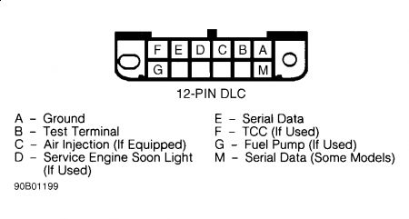
1. Turn ignition on with engine off. Malfunction Indicator Light (MIL) should glow. Locate Data Link Connector (DLC), attached to ECM wiring harness. Most DLCs are located under dash on driver's side of vehicle. For exact location of DLC, see appropriate COMPONENT LOCATIONS illustration in I - SYS/COMP TESTS article in this section. Turn ignition on. Insert jumper wire from terminal "B" (diagnostic test terminal) to terminal "A" (ground) of DLC. See Fig. 1.
NOTE: Inserting jumper wire into test and ground terminals of DLC with engine running will cause fuel-injected vehicles to enter field service mode and codes will not flash. See FIELD SERVICE MODE in BASIC TESTING article in this section.
2. Malfunction Indicator Light (MIL) should flash codes. Each code is flashed 3 times. If codes DO NOT flash, perform DIAGNOSTIC CIRCUIT CHECK (GASOLINE) in BASIC TESTING article in this section. To exit diagnostic mode, turn ignition off and remove jumper wire from DLC.

Monday, March 16th, 2009 AT 6:34 PM


