Wheel Hub, Bearing, and Seal Replacement (RWD)
Removal Procedure
Raise the vehicle. Refer to JACKING AND LIFTING in General Information.
Remove the tire and wheel. Refer to TIRE AND WHEEL REMOVAL AND INSTALLATION in Tires and Wheels.
Remove the brake rotor. Refer to BRAKE ROTOR (FRONT) in Disc Brakes.
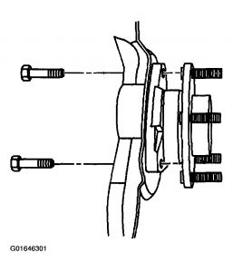
Remove the wheel hub and bearing mounting bolts.
Fig. 110: Removing Wheel Hub And Bearing
Courtesy of GENERAL MOTORS CORP.
Remove the wheel speed sensor mounting bolt from the wheel hub and bearing.
Disconnect the wheel speed sensor from the wheel hub and bearing.
Fig. 111: Disconnecting Wheel Speed Sensor
Courtesy of GENERAL MOTORS CORP.
Disengage wheel hub and bearing from steering knuckle.
Remove wheel speed sensor through the access hole in the splash shield.
Remove the wheel hub and bearing and splash shield.
Remove the splash shield form the wheel hub and bearing.
Fig. 112: Removing Splash Shield
Courtesy of GENERAL MOTORS CORP.
Installation Procedure
Install the splash shield to the wheel hub and bearing.
Install the wheel speed sensor through the access hole in the splash shield.
Install the wheel hub and bearing and splash shield to the steering knuckle.
Fig. 113: Installing Splash Shield
Courtesy of GENERAL MOTORS CORP.
Install the wheel speed sensor to the wheel hub and bearing.
NOTE:Refer to FASTENER NOTICE in Cautions and Notices.
Fig. 114: Installing Wheel Speed Sensor
Courtesy of GENERAL MOTORS CORP.
Install the wheel sped sensor mounting bolt to the wheel hub and bearing.
Tighten
Tighten the wheel speed sensor mounting bolt to 18 N.m (13 lb ft).
Install the wheel hub and bearing mounting bolts.
Tighten
Tighten the wheel hub and bearing mounting bolts to 180 N.m (133 lb ft).
Fig. 115: Installing Wheel Hub
Courtesy of GENERAL MOTORS CORP.
Install the brake rotor. Refer to BRAKE ROTOR (FRONT) in Disc Brakes.
Install the tire and wheel. Refer to TIRE AND WHEEL REMOVAL AND INSTALLATION in Tires and Wheels.
Lower the vehicle.

SPONSORED LINKS
Saturday, December 20th, 2008 AT 10:21 AM


