OPERATION
MAIN A/C-HEATER SYSTEM
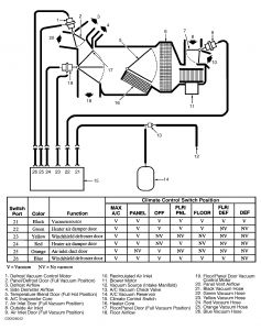
System airflow is controlled by a 6-port vacuum selector valve, an integral part of control panel. System air temperature is manually controlled by temperature control switch, which controls electric-actuated temperature blend-air door.
Blower motor electrical circuit uses ground side switching with blower switch and resistor assembly on ground side of motor, not battery side. This protects resistor assembly from overheating in event of an electrical short.
During system operation, with climate control switch in any setting except off and MAX A/C positions, blower motor draws in air directly into system through cowl air intake. In MAX A/C position, air flows from inside vehicle through recirculation duct. Once in system, air is blower driven through evaporator core and, depending on setting of temperature control switch, through and/or around heater core and into plenum. Air is directed from plenum to defrost nozzles, floor and instrument panel registers, depending on position of climate control switch.
VACUUM CONTROL MOTORS
Removal & Installation (Air Damper Door)
Disconnect vacuum hose connectors from vacuum control motor. Remove 2 retaining screws, rotate motor until shaft is clear of retainer. Lift shaft off mounting pin and remove vacuum control motor. To install, reverse removal procedure.
Removal & Installation (Defrost Door)
Disconnect vacuum hose connectors from vacuum control motor. Remove push-pin from end of shaft. Remove 2 mounting screws, and remove vacuum control motor. To install, reverse removal procedure.
Removal & Installation (Fresh/Recirculated Air Door)
Disconnect vacuum hose. Remove 2 screws retaining vacuum control motor. Rotate vacuum control motor until shaft is clear of retaining clip. Lift shaft off mounting pin, and remove vacuum control motor. To install, reverse removal procedure.

Sunday, November 30th, 2008 AT 6:04 PM


