Removal (With Manual Locking Hubs)
Raise and support front of vehicle. Remove front wheels. Remove 3 Torx screws securing locking hub cap assembly. Remove lock ring (seated in groove of wheel hub). Remove locking hub assembly from hub and brake rotor assembly. Remove brake caliper with brake line attached, and wire aside.
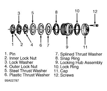
Remove snap ring. Noting position of thrust washers, remove 3 thrust washers from end of spindle (axle shaft). See Fig. 2 . Using Spanner Lock Nut Wrench (T85T-1197-A), remove hub bearing outer lock nut, lock washer and inner lock nut. Remove hub and brake rotor assembly. Outer bearing will slide off with hub. Remove grease seal and inner bearing. If bearings require replacement, remove races from hub with Internal Puller (T77F-1102-A) and attached slide hammer.
Fig. 2: Identifying Manual Locking Hub Components
Courtesy of FORD MOTOR CO.
I
nstallation & Adjustment
If bearings are replaced, drive NEW races into hub. Lubricate bearings with lithium base multipurpose wheel bearing grease. Install inner bearing and seal into hub. Install hub and rotor assemble on spindle.
Install inner lock nut. Using torque wrench and Spanner Lock Nut Wrench (T85T-1197-A) tighten inner lock nut to 50 ft. lbs. (68 N.m) while turning hub back and forth. Back off inner lock nut about 1/4 turn (90 degrees).
Install lock washer so key is positioned in front spindle groove. Tighten inner lock nut, aligning pin into nearest lock washer hole. Install outer lock nut and tighten to 160-205 ft. lbs. (217-278 N.m). Check hub and rotor assembly end play. End play should be 0-.002" (0-.05 mm). To complete installation, reverse removal procedure.

Monday, November 17th, 2008 AT 8:34 PM


