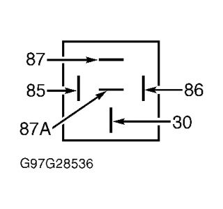
Check also for the rivet having poped off, more comon than not. That would be the actuator rivet. Troubleshooting the locks requires me to know what the problem is. HOW many locks do not work, and which ones? TEST A: ONE POWER DOOR LOCK INOPERATIVE 1. Manually operate inoperative door lock and check for binding or sticking lock. If door lock is not binding or sticking, go to next step. If door lock is binding or sticking, repair as necessary and recheck system operation. 2. Remove door trim panel and disconnect suspect door lock actuator connector. Use DVOM and measure voltage between ground and suspect door lock actuator connector terminal No. 1 (Pink/Black wire). Press door lock switch to LOCK position. If reading is 10 volts or greater, go to next step. If reading is less than 10 volts, repair open or short to ground in Pink/Black wire. See WIRING DIAGRAMS. Recheck system operation. 3. Use DVOM and measure voltage between ground and door lock actuator connector terminal No. 2 (Pink/Orange wire, Red/Orange wire if testing left front door lock actuator on models with remote keyless entry system). Press door lock switch to UNLOCK position. If reading is 10 volts or greater, replace suspect door lock actuator. See DOOR LOCK ACTUATOR under REMOVAL & INSTALLATION. If reading is less than 10 volts, repair open or short to ground in Pink/Orange wire or Red/Orange wire. See WIRING DIAGRAMS. Recheck system operation. TEST B: ALL POWER DOOR LOCKS INOPERATIVE 1. Turn ignition switch to OFF position. Check fuse No. 18 (25-amp) in Instrument Panel (I/P) fuse panel. I/P fuse panel is located behind driver's side of instrument panel. If fuse is okay, go to next step. If fuse is blown, replace fuse and recheck system operation. If fuse fails again, repair short to ground in power feed wire either to or from I/P fuse panel. 2. Locate auxiliary relay box No. 2 at right hand front of engine compartment. Check all terminals and connectors for door lock and unlock relays. If problem is found, repair as necessary. Recheck system operation. If no problem is found, go to next step. 3. Remove door unlock relay. Use DVOM and measure voltage between ground and terminals No. 86 (Black/White wire) and No. 87 (Black/White wire) at unlock relay connector. See Fig. 1 . If reading is 10 or more volts, repair open in Black wire between auxiliary relay box No. 2 and ground. Recheck system operation. Ground is located under driver's side of instrument panel, behind kick panel. If reading is less than 10 volts, repair poor connection or open in Black/White wire between I/P fuse panel and auxiliary relay box No. 2. Recheck system operation. Fig. 1: Identifying Door Lock & Unlock Relay Connector Terminals Courtesy of FORD MOTOR CO. TEST C: POWER DOOR LOCKS OPERATE FROM ONE SWITCH ONLY 1. Turn ignition switch to OFF position. Disconnect inoperative power door lock switch. Test door lock switch. Go to POWER DOOR LOCK SWITCH under COMPONENT TESTS. If switch tests okay, go to next step. If switch does not test okay, replace power door lock switch. See DOOR LOCK SWITCHES under REMOVAL & INSTALLATION. Recheck system operation. 2. With suspect switch disconnected, use DVOM and measure resistance between ground and following switch connector terminals: Page 2 of 7 POWER DOOR LOCKS -1998 Ford Explorer 8/9/2008
POWER DOOR LOCK SWITCH Remove door lock switch to be tested. Position switch with terminals facing upward, and raised part of rocker switch on left. See Fig. 2 or Fig. 3 . Check continuity between switch terminals with switch in specified position. See TESTING POWER DOOR LOCK SWITCHES table. Replace switch as necessary and recheck system operation. TESTING POWER DOOR LOCK SWITCHES Fig. 2: Identifying Door Lock Switch Terminals Courtesy of FORD MOTOR CO. Fig. 3: Identifying Liftgate Switch Terminals Courtesy of FORD MOTOR CO. NOTE: Door lock relay may also be referred to as door lock/unlock relay. Page 1 of 1 POWER DOOR LOCKS -1998 Ford Explorer 8/9/2008

SPONSORED LINKS
Saturday, August 9th, 2008 AT 11:31 AM


