IGNITION SWITCH
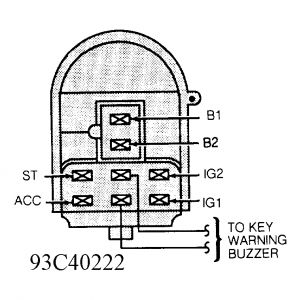
Test for continuity between specified terminals with switch in each position. See Fig. 2. If continuity is not as specified, or is poor in any switch position, replace ignition switch.
Fig. 2: Identifying Ignition Switch Terminals (Escort & Tracer)

Continuity should exist between terminals B1 and ST with switch in START position. Continuity should not exist with switch in any other position.
Continuity should exist between terminals B2 and ACC with switch in ACC or RUN position. Continuity should not exist with switch in any other position.
Continuity should exist between terminals B2 and IG1 with switch in START or RUN position. Continuity should not exist with switch in any other position.
Continuity should exist between terminals B1 and IG2 with switch in RUN position. Continuity should not exist with switch in any other position.
Continuity should not exist between terminals B1 and B2 with switch in any position.
Removal & Installation
Disconnect negative battery cable. Remove combination switch. See COMBINATION SWITCH under REMOVAL & INSTALLATION. Unplug ignition switch connector. Remove mounting screws and ignition switch. To install, reverse removal procedure.
COMBINATION SWITCH
Removal & Installation
Disconnect negative battery cable. Remove steering wheel. See STEERING WHEEL under REMOVAL & INSTALLATION. Remove upper and lower shrouds. Unplug connectors. Remove switch from housing. To install, reverse removal procedure.
STEERING WHEEL
CAUTION:When battery is disconnected, vehicle computer and memory systems may lose memory data. Driveability problems may exist until computer systems have completed a relearn cycle. See COMPUTER RELEARN PROCEDURES article in GENERAL INFORMATION section before disconnecting battery.
WARNING:Air bag system must be deactivated before any bag component is removed. See AIR BAG RESTRAINT SYSTEM article in the ACCESSORIES/SAFETY EQUIPMENT section.
Remove battery cables and do NOT touch the vehicle for 3 minutes .. air bag system is now deactivated ..
Removal & Installation
Disconnect negative battery cable. Disable air bag system. See AIR BAG RESTRAINT SYSTEM article in the ACCESSORIES/SAFETY EQUIPMENT section. Remove air bag module. Unplug clockspring connector from module. Remove steering wheel bolt, remove vibration damper (if equipped), and reinstall bolt loosely.
Remove steering wheel. Remove and discard steering wheel bolt. Hold clockspring in place with tape after removing steering wheel. To install, reverse removal procedure. Install and tighten NEW steering wheel bolt to specification. Check AIR BAG light to verify proper system operation.
Friday, December 14th, 2018 AT 9:40 AM
