Welcome to CarPros.
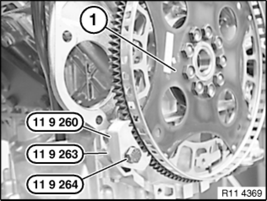
There is an alignment pin that has to be aligned for it to go on. Here are the specific directions for your vehicle. The attached pictures correlate with these directions.
__________________________________________
11 22 500 REMOVING AND INSTALLING/REPLACING FLYWHEEL
11 22 500 - Removing and installing or replacing flywheel (N51)
picture 1
Special tools required:
picture 2
Important!
Aluminium-magnesium materials.
No steel screws/bolts may be used due to the threat of electrochemical corrosion.
A magnesium crankcase requires aluminium screws/bolts exclusively.
Aluminium screws/bolts must be replaced each time they are released.
Aluminium screws/bolts are permitted with and without
color coding (blue).
For reliable identification:
Aluminium screws/bolts are not magnetic.
Jointing torque and angle of rotation must be observed without fail (risk of damage).
Picture 3
Necessary preliminary tasks:
- Remove transmission See: Manual Transmission/Transaxle > Removal and Replacement > 23 00 019 Removing and Installing Transmission (GS6-37BZ).
- Remove clutch.
Picture 4
Block flywheel (1) with special tool 11 9 260, use an old transmission screw for this purpose.
Installation Note:
Replace aluminium screws.
Unfasten flywheel screws.
Tightening torque: 11 22 1AZ. See: Flywheel > Mechanical > 11 22 Flywheel
Installation Note:
Flywheel (1) is secured with an alignment pin.
Fit new flywheel screws.
Clean crankshaft thread for flywheel screws.
Picture 5
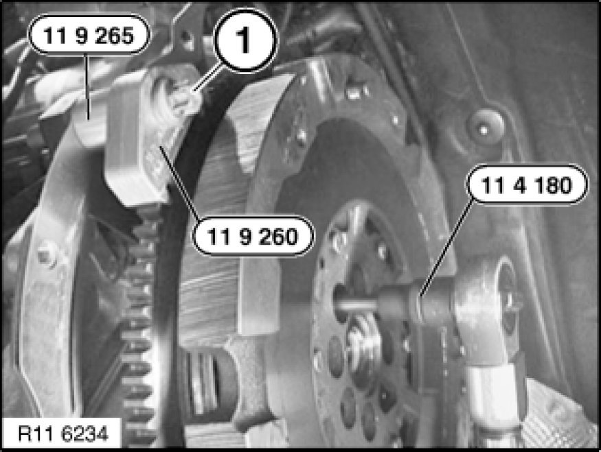
Secure flywheel with an old transmission screw (1) and special tools 11 9 260 and 11 9 265.
Installation Note:
Replace aluminium screws.
Release flywheel screws with special tool 11 4 180.
Installation Note:
Flywheel is secured with a dowel pin.
Fit new flywheel screws.
Tightening torque: 11 22 2AZ. See: Flywheel > Mechanical > 11 22 Flywheel
picture 6
Assemble engine.
Let me know if this helps or if you have other questions.
Take care,
Joe
Images (Click to make bigger)
Monday, April 8th, 2019 AT 7:35 PM

