The lamp module doesn't connect to those indicators in that way, it is an optional item and if you have it you could tell as it will show you if a particular light burns out or is disconnected. It monitors the headlights, tail lights and brake lights. The dash indicators connect to the turn signal feeds and flash with either selected light and both when hazards are selected. They get their power from the same feeds that power the front turn signals.
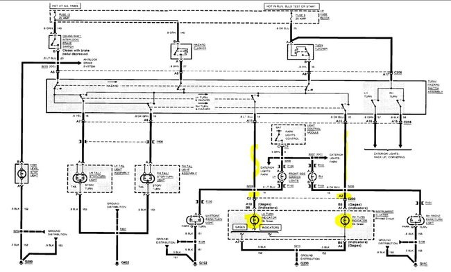
This is the basic schematic without the light monitor, the dash indicators work the same way on both, with the same wiring and colors, this one is just easier to read.
The highlighted pieces are the wires for the dash indicators. I would also start by pulling the dash and testing the two power feeds to the dash bulbs using a test light. The pins are different based on which display you have, if it has a full set of gauges like water temperature, oil pressure and volts the wires will be a light blue (left turn) at pin 10 in connector A and a dark blue (right turn) on pin 5 in connector B If the dash only has an oil light and a charge light then the positions change. The light blue wire is now at pin 9 in the B connector and the dark blue is at pin 1 in the A connector.
With the dash out and the connectors exposed you should be able to take a test light connected to ground and probe the two wires with the hazards on. The wires will have power when the front lamps flash on. If you find power on both but still have no indicators in the instrument cluster it is likely that the ground for the lamps has failed. It is a black wire and also changes if you have gauges or lights. With gauges it will be on pins 4 and 7 in connector A, if only lights cluster it will be pin 6 in connector B.
As both are out I suspect it's the ground connection as it's not likely that both splices and feeds failed at the same time, however it is possible they were damaged internally on the printed circuit board.
Image (Click to make bigger)
Thursday, April 8th, 2021 AT 12:36 AM


