Hi and thanks for using 2CarPros.com.
It sounds like you are right. Either the slave or the master cylinder has gone bad. Here are some general directions:
https://www.2carpros.com/articles/clutch-doesnt-work-sometimes-or-not-at-all
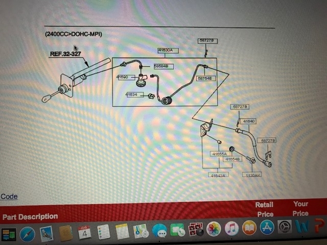
Here are the directions specific to checking the slave cylinder on your vehicle. Picture 1 correlates with these directions.
COMPONENT TESTS AND GENERAL DIAGNOSTICS
Inspection
1. Check the release cylinder bore for rust and damage.
2. Measure the release cylinder bore at three locations (bottom, middle, and top) with a cylinder gauge and replace the release cylinder assembly if the bore-to-piston clearance exceeds the limit.
Limit clearance to piston: 0.25mm (0.0098 in)
3. Check the clutch release cylinder for fluid leakage.
4. Check the clutch release cylinder boots for damage.
_________________________________________
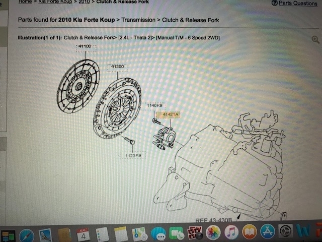
Here are the directions for replacing the slave cylinder if you find it bad. Pictures 2 through 5 correlate with these directions.
Removal
1. Drain the brake fluid through the bleed plug(A).
2. Disconnect the clutch tube(A).
3. Remove the two clutch release cylinder mounting nuts(B-2ea).
Installation
1. Coat the clutch clevis push rod specified grease.
Specified grease: CASMOLY L9508
2. Install the release cylinder mounting nuts(B-2ea).
Tightening torque :
15 - 22Nm (150 - 220 kgf.cm, 11 - 16 lb-ft)
3. Install the clutch tube(A).
4. Refill the brake fluid.
5. Bleed the air in the clutch system.
(refer to Bleeding in Service Adjustment Procedure)
_______________________________________________
Here are the directions specific to your vehicle for checking the clutch master cylinder. Pic 6 is an exploded view of the assembly. Picture 7 is the parts legend.
Inspection
1. Check the inside of the cylinder body for rust, pitting or scoring.
2. Check the piston cup for wear or distortion.
3. Check the piston for rust, pitting or scoring.
4. Check to make sure the clutch line tube is not clogged or restricted in any way.
5. Measure the master cylinder inside diameter and the piston outside diameter with a cylinder gauge micrometer.
NOTE:
Measure the inside diameter of the master cylinder at three places (bottom, middle, and top) in a perpendicular direction.
6. If the master cylinder-to-piston clearance exceeds the limit, replace the master cylinder and/or piston assembly.
Limit: 0.15 mm (0.006 in)
______________________________________________________
Here are the directions for removing and replacing plus, they include overhaul procedures. The remaining pictures correlate with these directions.
OVERHAUL
Removal
1. Drain the brake fluid through the bleeding plug (A).
2. Remove the flexible hose (A) connected to brake reserve tank from the master cylinder.
3. Disconnect the clutch tube (B) from the master cylinder.
4. Disconnect the two ignition lock switch connectors.
5. Remove the clutch pedal mounting nuts(A-2ea) and the bracket mounting nut.
6. Disconnect the push rod from the master cylinder by removing the snap pin (A) and washer (B).
7. Remove the screws mounting the master cylinder to the clutch pedal assembly.
1. Apply the specified grease to the clutch pedal and bushings.
Chassis grease: SAE J310a, NLGI No.1
2. Install the screws or nut mounting the master cylinder to the clutch pedal assembly.
3. Apply the specified grease to the snap pin(A) and washer.
Wheel bearing grease: SAE J310, NLGI No.2
4. Connect the push rod to the clutch pedal by installing the snap pin (A) and washer (B).
5. Install the clutch pedal mounting nuts (A-2ea).
Tightening torque :
17 - 26Nm (1.7 - 2.6kgf.m, 12.3 - 18.8Ib-ft)
6. Adjust the clutch pedal within the standard value, then secure by tightening the lock nut.
Standard value
Free play (A)
6 - 13mm (0.24 - 0.51 in)
Height (B)
182.8mm (7.19 in)
7. Connect the flexible hose of the brake reserve tank to the master cylinder.
8. Connect the clutch tube(B) to the master cylinder.
9. Refill the brake fluid.
10. Bleed the air in the clutch system.(refer to Bleeding in Serve Adjustment Procedure)
Disassembly
1. Remove the piston stop ring.
2. Pull out the push rod and piston assembly.
3. Remove the reserve tank band, reserve tank cap, and reserve tank.
NOTE:
1. Use care not to damage the master cylinder body and piston assembly.
2. Do not disassemble the piston assembly.
Inspection
1. Check the inside of the cylinder body for rust, pitting or scoring.
2. Check the piston cup for wear or distortion.
3. Check the piston for rust, pitting or scoring.
4. Check to make sure the clutch line tube is not clogged or restricted in any way.
5. Measure the master cylinder inside diameter and the piston outside diameter with a cylinder gauge micrometer.
NOTE:
Measure the inside diameter of the master cylinder at three places (bottom, middle, and top) in a perpendicular direction.
6. If the master cylinder-to-piston clearance exceeds the limit, replace the master cylinder and/or piston assembly.
Limit: 0.15 mm (0.006 in)
Reassembly
1. Apply the specified fluid to the inner surface of the master cylinder body (A) and to the entire periphery of the piston assembly (B).
Specified fluid: Brake fluid DOT 3 or DOT 4
2. Install the piston assembly.
3. Install the piston snap ring.
4. Install the push rod assembly.
_____________________________________________
I hope this is helpful. Let me know if you have other questions or need help.
Take care,
Joe
Images (Click to enlarge)
Aug 7, 2018 at 12:29 PM