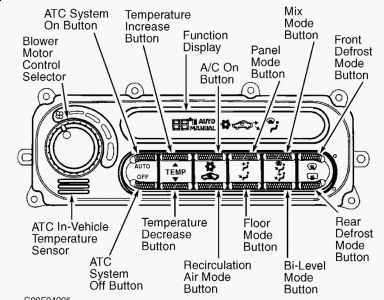
Code 26 is for the inside temp sensor, is that the one you replaced?
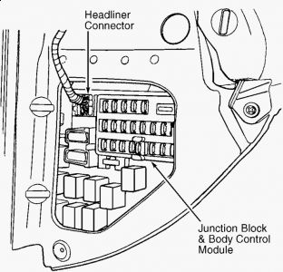
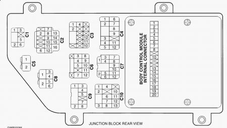
TEST 17A: INCORRECT BLOWER MOTOR SPEEDS 1. Turn ignition on and operate blower motor. If blower motor is stuck on high speed, go to next step. If blower motor is not stuck on high speed, replace ATC control head. Perform VERIFICATION TEST . 2. Locate Body Control Module (BCM), attached to junction block, at left end of instrument panel. See Fig. 4 . Turn ignition off. Remove BCM from junction block. Ensure 20-pin internal connector terminals are clean and tight. See Fig. 6 . Repair as necessary. 3. Using an ohmmeter, measure resistance between ground and junction block 20-pin internal connector terminal No. 20. If resistance is less than 5.0 ohms, go to next step. If resistance is more than 5.0 ohms, repair open in junction block ground circuit. Perform VERIFICATION TEST . 4. Using an ohmmeter, measure resistance between ground and junction block 20-pin internal connector terminal No. 1. If resistance is less than 5.0 ohms, go to next step. If resistance is more than 5.0 ohms, repair open in junction block ground circuit. Perform VERIFICATION TEST . 5. Disconnect blower motor power module 4-pin connector. Ensure connector terminals are clean and tight. Repair as necessary. Turn ignition on and engine off. Using a voltmeter, measure voltage between ground and power module 4-pin connector terminal No. 4 (Dark Green wire). If voltage is less than one volt, go to next step. If voltage is more than one volt, repair short to battery voltage in Dark Green wire. Perform VERIFICATION TEST . 6. Turn ignition off. Reconnect blower motor power module 4-pin connector. Connect a jumper wire between ground and BCM Black 24-pin connector C2 terminal No. 6 (Red/Light Green wire). Turn ignition on. If blower motor still operates at high speed, go to next step. If blower does not operate at high speed, replace BCM. Perform VERIFICATION TEST . 7. Turn ignition off and remove jumper wire. Disconnect blower motor power module 4-pin connector. Using an ohmmeter, measure resistance of Red/Light Green wire between BCM connector C2 terminal No. 6 and power module 4-pin connector terminal No. 3. If resistance is less than 5.0 ohms, go to next step. If resistance is more than 5.0 ohms, repair open in Red/Light Green wire. Perform VERIFICATION TEST . 8. Using an ohmmeter, measure resistance between ground and power module 4-pin connector terminal No. 2 (Black wire). If resistance is more than 5.0 ohms, repair open in Black wire. If resistance is less than 5.0 ohms, replace blower motor power module. Perform VERIFICATION TEST .
NOTE: Perform TEST 1A: IDENTIFYING ATC SYSTEM PROBLEMS before proceeding with this test.
VERIFICATION TEST 1. Reconnect all previously disconnected components and wiring. If Body Control Module (BCM) has not been replaced, go to next step. If BCM has been replaced, use DRB (scan tool) to program all Remote Keyless Entry (RKE) transmitters, recalibrate ATC system doors and program other options as necessary. 2. If ATC system has been repaired or battery has been disconnected, ATC door actuators must be calibrated. Start engine and use scan tool to calibrate door actuators. DO NOT allow vehicle to move during door actuator calibration. Turn engine off and go to next step. 3. Turn ignition on. Using scan tool, erase Diagnostic Trouble Codes (DTCs). Turn ignition off and wait at least 5 seconds. Turn ignition on (engine off) and fully operate repaired system to verify correct operation. If system operates properly, go to next step. If system does not operate properly, go to TEST 1A: IDENTIFYING ATC SYSTEM PROBLEMS . 4. If A/C-heater system operates properly, use scan tool to check for other BCM DTCs. If any BCM DTCs are present, go to TEST 1B: IDENTIFYING ATC SYSTEM BCM DIAGNOSTIC TROUBLE CODES test. If no BCM DTCs are present and original DTC cannot be duplicated, repair is complete.
Wednesday, October 7th, 2009 AT 12:49 PM
