Hello - Joe
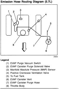
Well, based off of the code this deals with your catalytic converter and some with the O2 sensors. It did talk about the MAP sensors and it does have a vacuum hose. There are a few of your model trucks. Since you didn't specify I am giving you info for a 2500, V8-5.7L VIN R. If this isn't it let me know but I will need the exact model, and the exact engine as in liter and the 8th letter of your VIN.
After you review the pics. . .. . .. . .I would check the MAP sensor really good and see if the hose came off of that area. It is easier if you send a pic and try to see where it would naturally reach.
Next, I would as it says, look the cats over really good, etc.
If you find the hose goes to the MAP, then still look the cats over really good and the O2 sensors and wiring then clear the code and try it again.


Circuit Description
In order to control emissions of Hydrocarbons (HC), Carbon Monoxide (CO), and Oxides of Nitrogen (NOx), a three-way catalytic converter is used. The catalyst within the converter promotes a chemical reaction which oxidizes the HC and CO present in the exhaust gas, converting them into harmless water vapor and carbon dioxide. The catalyst also reduces NOx, converting it to nitrogen. The VCM has the capability to monitor this process using HO2S 2. HO2S 2, located in the exhaust stream past the three-way catalytic converter, produces an output signal which indicates the oxygen storage capacity of the catalyst; this in turn indicates the catalyst's ability to convert exhaust emissions effectively. If the catalyst is functioning correctly, the HO2S 2 signal will be far less active than that produced by HO2S 1. If a problem exists which causes the VCM to detect excessive HO2S 2 activity outside of an acceptable range for an extended period of time, the VCM will set DTC P0430, indicating that the three-way catalytic converter's oxygen storage capacity is below a threshold considered acceptable. Diagnostic Trouble Code (DTC) P0430 is a type A DTC.
Conditions for Setting the DTC
Converter Warm Up Test
A Closed Loop.
The commanded Air to Fuel ratio = 14.7:1.
The MAF is greater than 15 g/s.
The predicted Catalyst warm up temperature is greater than 450 °C.
Converter Warm UP Test Passed
No VS sensor DTCs.
No TP sensor DTCs.
No HO2S DTCs.
No misfire DTCs.
No MAP sensor DTCs.
No fuel trim DTCs.
No IAT sensor DTCs.
No ECT sensor DTCs.
No MAF sensor DTCs.
Engine coolant temperature is above 75 °C (167 °F).
The vehicle is in a Closed Loop fuel control.
The above conditions met for a period of time in order to ensure a warm catalyst (at least 2 consecutive minutes).
The calculated engine load is steady.
Vehicle speed is steady between 20 mph and 70 mph.
The IAT is at least -9.75 °C.
The MAF sensor is less than 50 g/s.
The engine speed is no more than 4700 RPM.
The TP sensor is more than 1.9%.
Action Taken When the DTC Sets
The VCM will turn ON the Malfunction Indicator Lamp (MIL).
Conditions for Clearing the MIL/DTC
The VCM turns the MIL off after 3 consecutive driving trips without a fault condition present. A history DTC will clear if no fault conditions have been detected for 40 warm-up cycles (coolant temperature has risen 40 °F from the start-up coolant temperature and the engine coolant temperature exceeds 160 °F during that same ignition cycle) or the scan tool clearing feature has been used.
Diagnostic Aids
Difficulty running the OBD II status DTC P0430 test may be encountered in areas where test conditions cannot be maintained easily, especially in urban areas. To minimize the amount of driving required to complete the test, use the following procedure:
Catalyst can be warmed up in service bay previous to drive cycle.
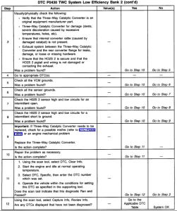
Engine also can be warmed up in bay also. HO2S 2 activity test: Using a scan tool, monitor MAP, HO2S 1, and HO2S 2 displays in Park or Neutral above idle. Compare HO2S 1 and HO2S 2 activity (amplitude and frequency) to each other during a 30 second period. If HO2S 2 activity is nearly as great as HO2S 1 activity, a problem exists; use diagnostic table on facing page. If much less activity is noted, system is functioning properly.
Test Description
Number(s) below refer to the step number(s) on the Diagnostic Table.
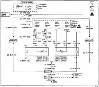
This table includes checks for conditions that can cause the three-way catalytic converter efficiency to appear degraded. Inspect and repair exhaust system as necessary per Exhaust System. Also inspect the HO2S 2 pigtail and engine harness for any damage that can cause an intermittent fault in HO2S 2 sensor signal HIGH and LOW circuits.
If the three-way catalytic converter needs to be replaced, make sure that another condition is not present which caused the catalyst to be damaged. These conditions include a) misfire; b) high engine oil consumption or coolant consumption; c) retarded spark timing or weak spark. To avoid damaging the replacement three-way catalytic converter, correct engine misfire or mechanical fault before replacing three-way catalytic converter.

PURPOSE
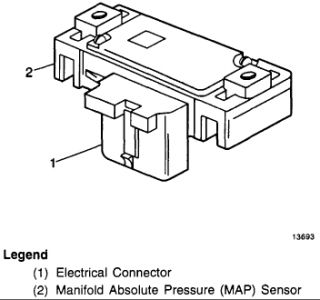
The Manifold Absolute Pressure (MAP) sensor responds to changes in the intake manifold pressure. The pressure changes as a result of engine load and speed. The map sensor converts this to a voltage output.
OPERATION
A closed throttle on engine coast down would produce a relatively low MAP output voltage. A wide open throttle would produce a high MAP output voltage. This high output voltage is produced because the pressure inside the manifold is the same as outside the manifold. The MAP is inversely proportional to what is measured on a vacuum gage. The MAP sensor is used for the following:
Altitude determination.
Ignition timing control.
Exhaust Gas Recirculation (EGR) diagnostic.
Speed density fuel management default.

SPONSORED LINKS
Friday, October 31st, 2008 AT 7:48 PM


