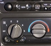
Use a meter to see if the switch is open or closed on 1, 2, 4, 5. If open, replace the switch. It may be a complete control module replacement.
MANUAL AIR CONDITIONING HEATER SYSTEM -2002 Chevrolet Malibu
Page 1 of 2
TEST E: BLOWER MOTOR MALFUNCTION
NOTE:
For correct circuit identification and connector terminal locations, see
CONNECTOR IDENTIFICATION and/or WIRING DIAGRAMS.
NOTE:
Definition: The blower motor operates in at least one, but not all, speed positions.
Perform DIAGNOSTIC SYSTEM CHECK
step.
Turn ignition on, engine off. Place mode switch in VENT position. Place blower motor switch in each speed position. If blower motor operates at desired speed in each speed position, problem is
intermittent. Check wiring and connections. If blower motor does not operate at desired speed in each speed position, go to next step.
Turn ignition off. Disconnect blower motor. Turn ignition on, engine off. Connect a test light between blower motor supply voltage circuit and ground. Place blower motor switch in each
speed position. If test light illuminates in each speed position, go to step 14. If test light does not illuminate in each speed position, go to next step.
If test light illuminates in maximum speed position, go to step 9 in maximum speed position, go to next step.
Turn ignition off. Disconnect blower motor relay. Turn ignition on, engine off. Connect a test light between battery positive voltage circuit of blower motor relay and ground. If test light
illuminates, go to next step. If test light does not illuminate, go to step 17.
Place blower motor switch in maximum speed position. Probe blower motor relay high blower motor control circuit with a test light connected to ground. If test light illuminates, go to step 8. If
test light does not illuminate, go to next step.
Test blower motor relay high blower motor control circuit for an open or high resistance. Repair as necessary, then go to step 22. If circuit is okay, go to step 16.
Test blower motor relay ground circuit for an open or high resistance. Repair as necessary, then go to step 22. If circuit is okay, go to step 13.
Turn ignition off. Disconnect blower motor relay. Turn ignition on, engine off. Probe blower motor supply voltage circuit with a test light connected to ground. Place blower motor switch in
minimum, medium "1", medium "2", and medium "3" speed positions. If test light illuminates in each speed position, go to step 13. If test light does not illuminate in each speed position, go to
next step.
Test blower motor supply voltage circuit between blower motor resistor and blower motor relay for an open, short to ground, or high resistance. Repair as necessary, then go to step 22. If circuit
is okay, go to next step.
1.
Under SELF-DIAGNOSTIC SYSTEM. Go to next. If test light does not illuminate
E:
Blower motor switch must be placed in appropriate speed position for blower motor control circuit being tested.
11.
Turn ignition off. Disconnect blower motor resistor. Turn ignition on, engine off. Probe low, medium "1", medium "2", and medium "3" blower motor control circuits with a test light
connected to good ground. Place blower motor switch in appropriate speed position for circuit being tested. If test light illuminates in each speed position, go to step 15. If test light does not
12/30/2011
MANUAL AIR CONDITIONING HEATER SYSTEM -2002 Chevrolet Malibu
Page 2 of 2
illuminate in each speed position, go to next step.
Test applicable blower motor control circuit of blower motor resistor for an open or high resistance. Repair as necessary, then go to step 22. If circuit is okay, go to step 16.
Inspect for poor connections at blower motor relay harness connector. Repair as necessary, then go to step 22. If connections are okay, go to step 18.
Inspect for poor connections at blower motor harness connector. Repair as necessary, then go to step 22. If connections are okay, go to step 19.
Inspect for poor connections at blower motor resistor harness connector. Repair as necessary, then go to step 22. If connections are okay, go to step 20.
Inspect for poor connections at HVAC control assembly harness connector. Repair as necessary, then go to step 22. If connections are okay, go to step 21.
Repair blower motor relay battery positive voltage circuit. After repairs are complete, go to step 22.
18. Replace blower motor relay. See BLOWER MOTOR RELAY under REMOVAL & INSTALLATION. After repairs are complete, go to step 22.
19. Replace blower motor. See BLOWER MOTOR under REMOVAL & INSTALLATION. After replacement, go to step 22.
Replace blower motor resistor. See BLOWER MOTOR RESISTOR
INSTALLATION. After replacement, go to step 22.
21. Replace HVAC control assembly. See HVAC CONTROL ASSEMBLY under REMOVAL & INSTALLATION. After repair, go to next step.
Operate A/C-heater blower system to verify repair. If blower motor operates normally, repair is complete. If blower motor still malfunctions, go to step 3.
Under REMOVAL &
Wednesday, October 28th, 2020 AT 12:54 PM
(Merged)


