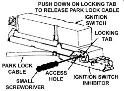
Disconnect the negative battery cable.
If equipped, properly disable the SIR system
Remove the left side lower trim panel.
Remove the steering column-to-support screws and lower the steering column.
Unplug the dimmer switch and turn signal switch connectors.
Remove the wiring harness-to-firewall nuts.
Remove the steering column-to-steering gear bolt and remove the steering column from the vehicle.
Remove the combination switch.
Place the lock cylinder in the RUN position.
Remove the steering shaft assembly and turn signal switch housing as an assembly.
Using the terminal remover tool No. J 35689A or equivalent, label and unplug the wires F and G on the connector at the buzzer switch assembly from the turn signal switch electrical harness connector.
With the lock cylinder in the RUN position, remove the buzzer switch.
Place the lock cylinder in the ACCESSORY position, remove the lock cylinder retaining screw, and remove the lock cylinder.
Remove the dimmer switch nut/bolt, the dimmer switch, and the actuator rod.
Remove the dimmer switch mounting stud (the mounting nut was attached to it).
Remove the ignition switch-to-steering column screws and the ignition switch.
Remove the lockbolt screws and the lockbolt.
Remove the switch actuator rack and ignition switch.
Remove the steering shaft lock and spring.

To install:
To install the lockbolt, lubricate it with lithium grease and install the lockbolt, spring and retaining plate.
Lubricate the teeth on the switch actuator rack, install the rack and the ignition switch through the opening in the steering bolt until it rests on the retaining plate.
Install the steering column lock cylinder set by holding the barrel of the lock cylinder, inserting the key and turning the key to the ACCESSORY position.
Install the lock set in the steering column while holding the rack against the lockplate.
Install the lock retaining screw. Insert the key in the lock cylinder and turn the lock cylinder to the START position and the rack will extend.
Center the slotted holes on the ignition switch mounting plate and install the ignition switch mounting screw and nut.
Install the dimmer switch and actuator rod into the center slot on the switch mounting plate.
Install the buzzer switch and turn the lock cylinder to the RUN position. Push the switch in until it is bottomed out with the plastic tab that covers the lock retaining screw.
Install the steering shaft and turn signal housing as an assembly.
Install the turn signal switch. Install the steering wheel to the column, and tighten the steering shaft nut to 30 ft. lbs. (41 Nm).
Install the steering column in the vehicle. Connect all electrical leads. Install the lower trim panels.
Connect the negative battery cable.
If equipped, properly enable the SIR system
Check steering column operations.
Tuesday, March 2nd, 2010 AT 4:31 PM
