Hi Stevey818,
Thank you for the donation.
The is an onboard self-diagnostic system that you can use. Try it and see if you can come up with anything.
SELF - DIAGNOSTIC SYSTEM
NOTE: Electronic Control Module (ECM) and Powertrain Control Module (PCM) are same system; terms are often used interchangeably.
Self -diagnostic system consists of 4 components. These components are Powertrain Control Module (PCM), Instrument Panel Cluster (IPC) options, A/C Programmer (ACP) options and Supplemental Inflatable Restraint (SIR) system.
In addition to monitoring a particular set of sensors and switches, PCM maintains continuous communication with each system component. Should a component exceed pre-programmed limits, PCM will recognize a malfunction and may act to control malfunctioning component. To control a particular component, PCM rapidly switches an internal circuit between zero and 5 volts, converting programmed control information into series of pulses that represents coded serial data messages. These messages are transmitted to malfunctioning component, which interprets information and responds accordingly.
As a result, an alphanumeric code, known as a trouble code, is often set in PCM memory. This trouble code identifies malfunctioning component and can be accessed by a service technician as an aid to diagnostic procedures. All trouble codes are displayed on Driver Information Center (DIC) panel.
In addition to monitoring self -diagnostic system and displaying trouble codes, PCM can be programmed by service technician to perform specific diagnostic tests on individual components and systems. Results of these tests are displayed on DIC. This article covers accessing PCM trouble codes and programming self -diagnostic system to perform specific diagnostic tests on system components.
ENTERING SELF - DIAGNOSTICS
1 . Turn ignition on. Simultaneously push OFF and WARMER buttons on Climate Control Panel (CCP). Continue pushing OFF and WARMER buttons until segment check appears (about 3 seconds) on Instrument Panel Control (IPC).
NOTE: Failure of any segment to glow may result in inaccurate test results. Replace any inoperative segment display before proceeding with self-diagnostic process.
2 . When segment check appears (all segments glow), system has entered into self -diagnostic mode. Release both buttons. Driver Information Center (DIC) will display diagnostic codes. Diagnostic code level displays PCM codes first, followed by IPC, ACP and SIR codes (if so prompted).
3 . To proceed to desired level, press and release CCP panel HI (fan up) button for "yes" or LO (fan down) button for "no". Depress LO button to go to next test level (i.e., IPC?, ACP? or SIR?) or depress OFF button to return to next selection in previous test level.
4 . To exit diagnostics, press AUTO button on IPC. System will go back to normal vehicle operation.
DISPLAYING TROUBLE CODES
1 . Diagnostic code level displays PCM codes first, followed by IPC, ACP and SIR codes (if so prompted). Trouble codes appear in ascending (3 -digit) numerical order and are prefixed by "P" (PCM), "I" (IPC), "A" (ACP) or "R". A final digit of either a "C" (current) or "H" (history)" will also be indicated on every code.
2 . For complete list of available PCM trouble codes, see PCM TROUBLE CODES table. If no codes are present for a system, a "NO X CODE" message (with X being system, i.e. "P", "I", etc.) will be displayed. If communication line to a component is not operating, a "NO X DATA" message will be displayed, indicating that IPC could not communicate with that system.
3 . To continue with system diagnostics, see SERVICE MODE OPERATION. To exit from SERVICE MODE and go back to normal vehicle operation, depress AUTO button on IPC.
PCM TROUBLE CODE DEFINITIONS
Code Test Condition
P012 (1) No Distributor (TACH) Signal
P013 (1) (5) Rear Oxygen Sensor Not Ready
P014 (1) Shorted Coolant Sensor Signal
P015 (1) Open Coolant Sensor Signal
P016 (2) Alternator Voltage Out Of Range
P017 (1) Front Oxygen Sensor Not Ready
P019 (2) Shorted Fuel Pump Feedback Signal
P020 (2) Open Fuel Pump Circuit
P021 (1) Shorted TP Sensor Circuit (Signal Voltage High)
P022 (1) Open TP Sensor Circuit (Signal Voltage Low)
P023 (1) Ignition Control Circuit Problem
P024 (1) (6) Vehicle Speed Sensor (VSS) Circuit Problem
P025 (2) 24X Reference Signal Low
P026 (1) Shorted Throttle Switch Circuit
P027 (1) Open Throttle Switch Signal
P028 (1) Transaxle Pressure Switch/Circuit Problem
P029 (1) Transaxle Shift "B" Solenoid Problem
P030 (1) ISC RPM Out Of Range
P031 (1) Shorted MAP Sensor Circuit
P032 (1) Open MAP Sensor Circuit
P033 (2) Extended Travel Brake Switch Input Circuit Problem
P034 (1) MAP Sensor Signal Too High
P035 (3) Ignition Ground Voltage Out Of Range
P036 (1) Exhaust Gas Recirculation (EGR) Valve Pintle Position Out Of
Range
P037 (1) Shorted Intake Air Temp (IAT) Sensor Signal
P038 (1) Open Intake Air Temp (IAT) Sensor Signal
P039 (1) (4) TCC Engagement Problem
P040 (1) Open PSPS Circuit
P041 (1) No CAM Sensor Signal
P042 (1) (5) Front Oxygen Sensor Lean Signal
P043 (1) (5) Front Oxygen Sensor Rich Signal
P044 (1) (5) Rear Oxygen Sensor Lean Signal
P045 (1) (5) Rear Oxygen Sensor Rich Signal
P046 (1) Front-To-Rear Bank Fueling Imbalance
P047 (1) IPC -To-PCM Data Problem
P048 (1) EGR System Fault
P051 (1) PROM Error
P052 (3) PCM Memory Reset
P053 (3) Distributor Signal Interrupt
P055 (3) TP Sensor Out Of Range
P056 (1) Transaxle Input Speed Sensor Circuit Problem
P058 (3) Pass-Key Fuel Enable Problem
P060 (3) Cruise Control With Transaxle Not In Drive
P061 (3) Cruise Control Vent Solenoid Problem
P062 (3) Cruise Control Vacuum Solenoid Problem
P063 (3) Vehicle Speed & Set Speed Difference Too High
P064 (3) Cruise Control Engaged/Acceleration Too High
P065 (3) Cruise Control Servo Position Sensor Failure
P066 (3) Engine RPM Too High With Cruise Engaged
P067 (3) Set/Coast Or Resume/Accel Switch Shorted
P068 (3) (6) Cruise Control Servo Position Out Of Range
P069 (7) Traction Control Active While In Cruise
P070 (3) Intermittent TP Sensor Signal
P071 (3) Intermittent MAP Sensor Signal
P073 (3) Intermittent Coolant Temp Sensor Signal
P074 (3) Intermittent Intake Air Temp Sensor Signal
P075 (3) VSS Signal Interrupt
P076 (1) Transaxle Pressure Control Solenoid Circuit
P080 (1) Fuel System Rich
P081 (3) CAM To 4X Reference Correlation Problem
P083 (1) 24X Reference Signal High
P085 (1) Idle Throttle Angle Too High
P086 (1) Undefined Gear Ratio
P088 (1) Torque Converter Clutch (TCC) Not Disengaging
P089 ( 8 ) Long Shift And Maximum Adapt
P090 (2) TCC Brake Switch Input Problem
P091 (2) Transaxle Range Switch Problem
P092 (2) Heated Windshield Request Problem
P093 (9) Traction Control System Pwm Link Failure
P094 (1) Transaxle Shift 'A' Solenoid Problem
P095 Engine Stall Or Near Stall Detected
P096 (1) Torque Converter Overstress
P097 (3) Park/Neutral - To-Drive/Reverse Shift At High Throttle Angle
P098 (3) Park/Neutral - To-Drive/Reverse Shift While In ISC Control
Range
P099 (3) Cruise Servo Applied Not In Cruise
P0102 (2) Shorted Brake Booster Vacuum (BBV) Sensor
P0103 (2) Open Brake Booster Vacuum (BBV) Sensor
P0105 (2) Brake Booster Vacuum (BBV) Too Low
P0106 (9) Stop Lamp Switch Input Circuit Problem
P0110 (10) Generator "L" Terminal Circuit Problem
P0112 EEPROM Failure
P0117 (1) Shift "A"/Shift "B" Solenoid Circuit Open Or Shorted
P0131 Active Knock Sensor Failure
P0132 (1) Knock Sensor Circuit Failure
P0137 (11) Loss Of ABS/TCS Data
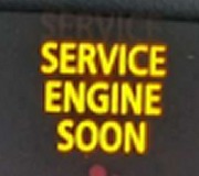
(1) This fault turns on SERVICE ENGINE SOON light.
(2) This fault turns on SERVICE VEHICLE SOON message.
(3) This fault does not turn on any light or message.
(4) This fault disengages TCC for ignition cycle.
(5) This fault enables EVAP control solenoid.
(6) This fault disables cruise control for ignition cycle.
(7) PCM disables cruise control.
( 8 ) Code sets, no service telltale.
(9) DIC message displayed "TRACTION DISABLED".
(10) DIC message displayed "BATTERY NO CHARGE".
(11) PCM sets all serial data from the Anti -Lock Brake Traction Control System to zero.
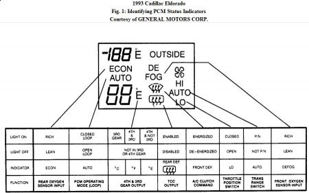
STATUS LIGHTS DISPLAY
Upon entering PCM system level of self -diagnostic mode, indicator lights on DIC automatically
indicate operational status of TCC, certain emission control components and A/C compressor
operation. Operational status of these components is indicated by corresponding status light being
on or off.

NOTE: IPC, ACP and SIR systems can also be tested in SERVICE MODE. Only information related to PCM diagnosis is in this article.
After PCM trouble codes have been displayed, SERVICE MODE can be used to exit diagnostics or individually perform other tests on different systems.
Selecting System Level
Following trouble code display, first available system will be displayed (i.e., IPC?). When selecting a system to test, any of following actions may be taken to control display:
1 . Depressing HI (fan up) button on CCP will select displayed system for testing (i.e., PCM DATA, PCM INPUTS, PCM OUTPUTS, etc.).
2 . Depressing LO (fan down) button on CCP will display next available system selection (i.e., IPC?, ACP? or SIR?). This allows display to be cycled through all system choices. This list of systems can be repeated following end of system list.
3 . Depressing OFF button on CCP will stop system selection process and return display to beginning of PCM trouble code sequence.
Selecting Test Type Level
Selection of PCM DATA, PCM INPUTS, PCM OUTPUTS, PCM OVERRIDES, PCM CLEAR
CODES or PCM SNAPSHOT test may be displayed. If dashes appear in DIC, test is not valid or test conditions are wrong. While selecting a specific test, any of following actions may be taken to control display:
1 . Depressing HI (fan up) button on CCP will display a specific output or test parameter for selected test type level (i.e., PCM data parameter PD01, etc.).
2 . Depressing LO (fan down) button on CCP will display next test type level for system level (i.e., PCM INPUTS?, PCM OUTPUTS?, etc.). This allows display to be cycled through all available test type choices. This list of test types can be repeated following
display of last test type.
3 . Depressing OFF button on CCP will stop test selection process and return display to next system level (i.e., IPC?).
Selecting Clear Codes
Selecting PCM CLEAR CODES test will result in PCM CODES CLEAR message being displayed with selected system name for 3 seconds, indicating all stored trouble codes have been erased from memory. After 3 seconds, display will automatically return to next available test type level (i.e., PCM SNAPSHOT?).
After a code has been cleared, make a complete ignition cycle and possibly a test drive. Ensure
code does not reset.
PCM LOCATION
PCM is located behind right side of dash, above kick panel.
SPONSORED LINKS
Monday, September 21st, 2009 AT 5:06 AM


