Ok I see what you are saying, so there are 2 different designs when it comes to the door switches,
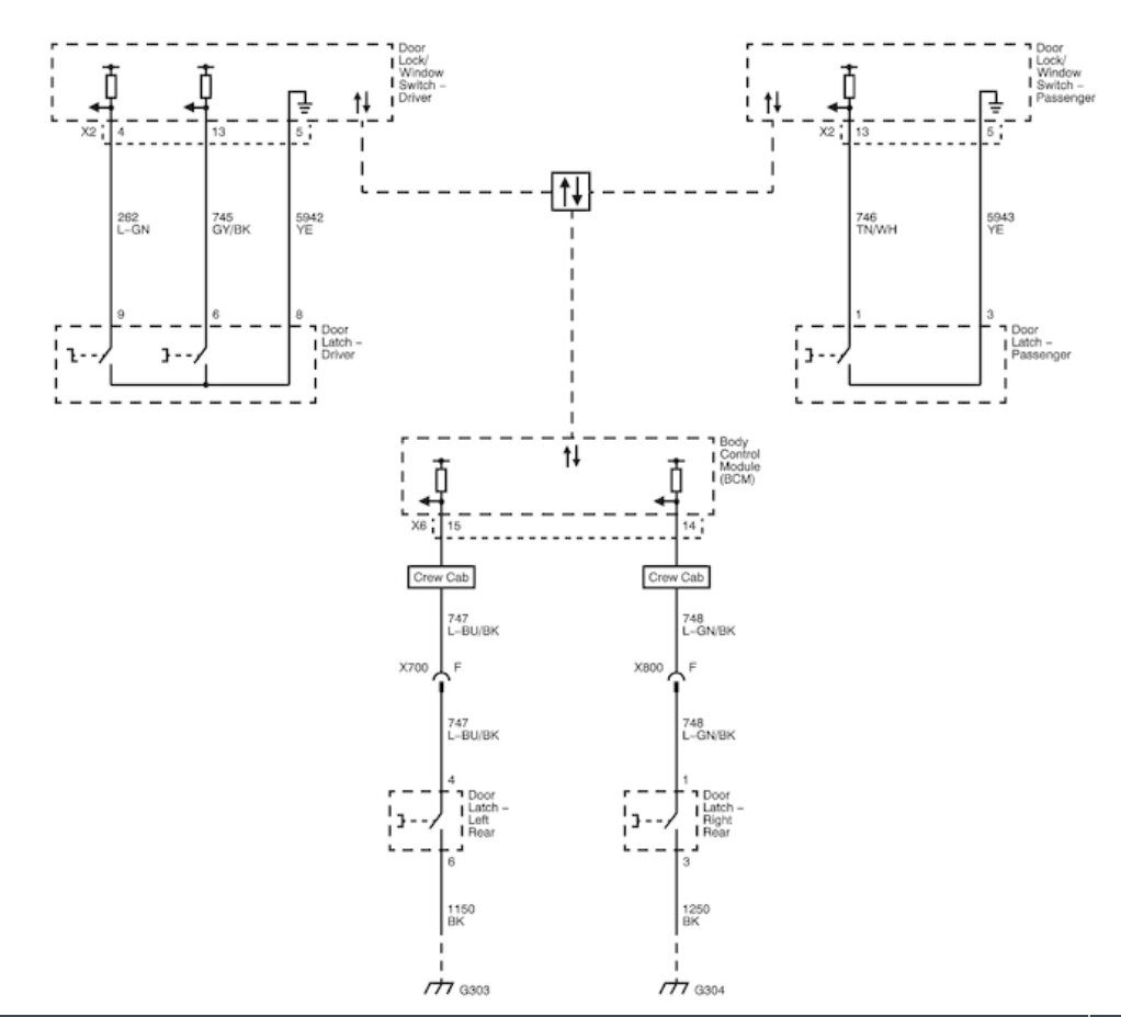
The first has the front door switch/latch signals going to the Door/Lock Window switch driver (or module). This is in each driver and passenger front door. Then these switch modules communicate to the Instrument Cluster via the GMLAN bus network. Then the rear doors input to directly to the BCM which in turn communicates to the Instrument Cluster on the GMLAN to indicate that a door is a jar. (Diagram 1)
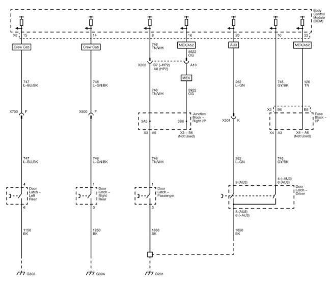
The 2nd design, which is labelled (without AN3 or DL3), the BCM receives inputs from the front and rear doors directly, then the BCM communicates this to the Cluster via the GMLAN. Which you can see in the 2nd diagram.
Hopefully these aftermarket diagrams are correct, but service info is stating that with Bucket Seats and Power Mirrors, you should have the 2nd design, where everything is directly input into the BCM, thankfully.
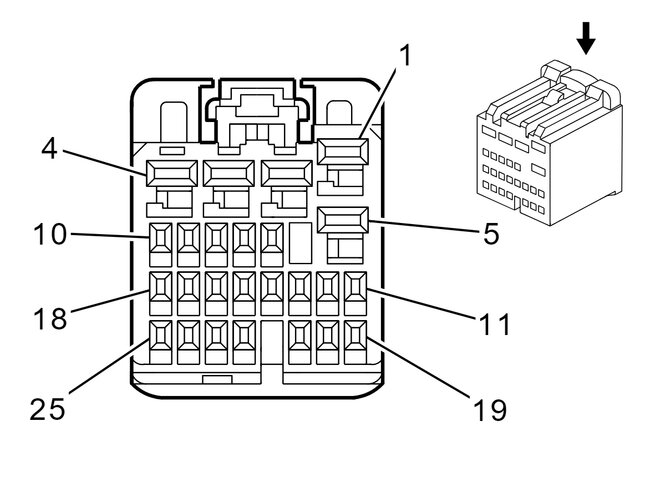
So the 2nd diagrams should be your vehicle, I will pull up the X6 BCM connector that should have all the door inputs directly on that connector. Give me a minute to find this connector pinout. And you can verify the wire colors from there.
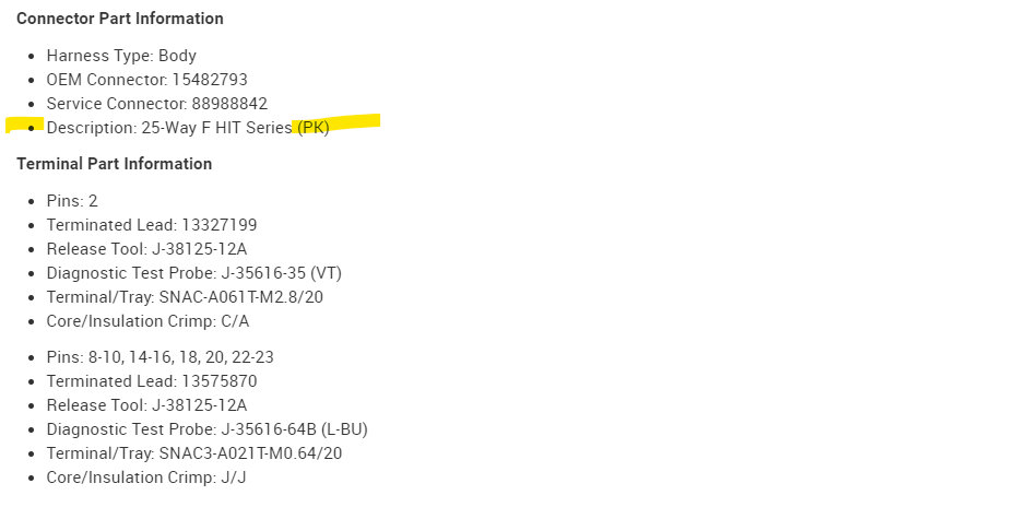
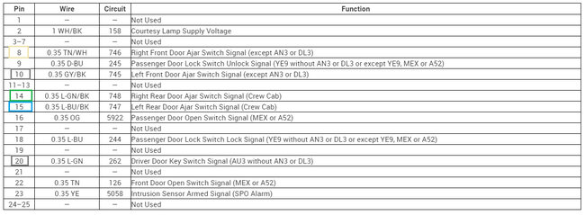
It looks like BCM connector X6 is a Pink connector, and the only pin Im not 100% sure on is the driverside door switch, they have pins 10 and 20 labelled as the input depending on this AU3 factor, I believe that pin 20 is just a Key In input pin to the BCM, whereas pin 10 Grey/Black wire us the driver door Ajar signal. The rest of the switches are listed in diagram 8. These are pull down circuits, so the BCM pin should read 12 or 5 volts until the door is closed then it should drop the 0volts, its most likely a 12volt feed, but there is a resistor inside the BCM, so they are pull down circuits. Im not sure what the instructions are for the runner boards, if they are to be powered off of the door switches or if it comes with a control module, I dont think these door switches are designed to pull high current threw the BCM on these wires to the switches, so be careful with that. You dont want to burn out the BCM.
If the BCM connectors are not different colors, you should be able to identify them by the wire coloring and the wire locations in the X6 connector. But disregard the 1st diagram below, that shouldnt be for your vehicle. That one has the door modules communicating on the network.
Images (Click to make bigger)
Thursday, July 6th, 2023 AT 12:21 PM
