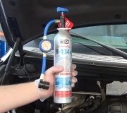
First you need to drain the oil from the AC compressor and measure the amount so you can put in the same amount of "PAG" oil. Draining usually requires removing the compressor. You can get the adapter fittings from the dealer, a radiator repair shop, or most auto parts stores. Many parts suppliers will only sell AC system parts to licensed mechanics. That varies by state and how much the politicians need to control you.
Since your system apparently needs to be recharged, you have to wonder if that's because there's a leak or it's normal seepage due to age. A leak has to be repaired, otherwise most states will not allow a mechanic to recharge the system. Be aware that R-134 molecules are much smaller than R-12 molecules, so R-134 leaks out a lot faster. On systems that came with R-134, the rubber hoses have nylon liners to reduce refrigerant loss. We used to have new hoses made as part of retrofits, but now we just change the oil and add the fittings. Rubber is porous so you can expect to have to recharge a retrofitted system much more often.
Once any repairs are completed, you can't just dump in the refrigerant. There will be air in the system with moisture, (humidity). That moisture will form droplets that will freeze and block refrigerant flow at the expansion valve. The symptom is the system will cool fine for 15 - 20 minutes, then blow warm air for perhaps half an hour until the ice melts. The system has to be pumped into a vacuum for at least half an hour first. That causes water to boil at 77 degrees so it can be drawn out. That vacuum will pull in some of the refrigerant, but charging stations use a pump to finish filling the system under pressure. It is critical that the exact measured amount of refrigerant be installed. This is definitely not a case of "more is better". Some of the refrigerant will be a liquid and some will be a vapor. The point where liquid turns to vapor is where it gets real cold. You want that to be right in the middle of the evaporator in the dash. If there's too little charge, the cooling will take place under the hood, not where the incoming air travels. If there's too much refrigerant, the cooling will take place in the hose under the hood that goes to the compressor. Even worse, if liquid gets into that hose, it can slosh into the compressor and destroy it. Compressor can't compress a liquid; only a vapor.
As for the vacuum lines, if you have a carburetor, you don't have a MAP sensor. MAP sensors are only used on fuel injected engines and those use a throttle body. You're right in the middle of when they were switching over to throttle bodies. If you do have a MAP sensor, all that's required is it is connected to intake manifold vacuum without going through any valves. The shorter that hose is, the better. The hose to the power brake booster would not be my first choice because at low engine speeds or high loads, vacuum is already fairly low, then applying the brake pedal multiple times can reduce it even more in that hose because it takes such a high volume to build it back up. MAP sensors are so sensitive, they could be used to measure engine speed by counting the little pulses of increased vacuum each time a piston takes a gulp of air. We don't actually do that, but because they are so sensitive, a fault code can be set related to "pneumatic failure", meaning the sensor is still working properly but there's something wrong with the vacuum source.
Your best bet for the correct vacuum diagram is to visit your local library. I'm in mine right now, and they have hundreds of Chiltons and Haynes manuals. I normally don't like them or recommend them, but for something like this, their diagrams come right out of the manufacturer's manuals.
It's normal for the cruise control vacuum to tap off the check valve on the power brake booster. Around the late '80s, the MAP sensor was usually mounted on the right front strut tower, and a three-foot-long hose ran to a port on the intake manifold or after the throttle blade on the throttle body. There was a problem with condensed fuel vapors settling in the middle of that hose. That would cause the pneumatic failure fault code I mentioned. The fuel blocked the hose. It would move with changes in vacuum, but not fast enough. It dampened the tiny variations in vacuum and resulted in that fault code. The solution for that was to cut the hose a few inches from each end, install vacuum "tees", then run a second hose between the two tees. It looks like that doesn't make any sense, but it allowed the fuel to circulate and be drawn off and burned. That fix was very effective. On newer vehicles the MAP sensors were mounted closer to the intake manifold, and by the late '90s their vacuum ports were plugged right into the intake or throttle body. No more hose to deal with.
Thursday, July 21st, 2016 AT 3:42 PM


