Hello. Thanks for the donation. Much appreciated
The symptoms your describing sound exactly like a faulty MAF (mass airflow) sensor would cause. This should set it's own fault code. But not always?
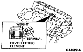
TEST DG: KNOCK SENSOR (KS)
Diagnostic Aids
Perform this test only when directed by QUICK TEST. This test is intended to diagnose the following:
Knock Sensor (KS)
Harness Circuit: KS
Powertrain Control Module (PCM)
To prevent replacement of good components, be aware the following non-EEC related areas may be at fault:
Poor Fuel Quality
Ignition Timing
Engine Mechanical Condition
CIRCUIT PIN IDENTIFICATION
CircuitPCM Pin No. Wire Color
KS63White
GND45Black/Red
NOTE:Freeze frame data will not be stored in the ECM for the knock sensor. The MIL will not light for a knock sensor malfunction.
DTC P0325
DTC P0325 indicates that spark knock has occurred and knock sensor failed to detect. Possible causes for this fault are as follows:
PCM not receiving signal.
Open or short in harness.
Faulty knock sensor.
Faulty Powertrain Control Module (PCM).
Turn ignition off. Disconnect PCM. Disconnect knock sensor in-line connector. Measure resistance of KS signal circuit (White wire) between PCM connector terminal No. 63 and KS in-line connector. Measure resistance of GND circuit (Black/Red wire) between PCM harness connector terminal No. 45 and KS in-line connector. If resistances are less than 5 ohms, go to next step. If resistances are more than 5 ohms, repair open in White or Black/Red wires. See Fig. 11. See CIRCUIT PIN IDENTIFICATION table.
Check KS Circuit For Short To Ground
Disconnect PCM. Disconnect KS in-line connector. Measure resistance of KS circuit between PCM connector terminal No. 63 (White wire) and GND terminal No. 45 (Black/Red wire). If resistance is more than 10 k/ohms, go to next step. If resistance is less than 10 k/ohms, repair short circuit in wiring.
Fig. 11: Identifying KS Sensor Connector Terminals
Courtesy of FORD MOTOR CO.
Check KS Circuits For Short To Power
Disconnect PCM. Disconnect KS in-line connector. Measure resistance of KS circuit between PCM connector terminal No. 63 (White wire) and VPWR terminals No. 66 and 97 (Black/White wires). Measure resistance between PCM connector terminal No. 63 (White wire) and KAPWR terminal No. 80 (Yellow wire). If each resistance measurement is more than 10 k/ohms, go to next step. If each resistance measurement is less than 10 k/ohms, repair short circuit in wiring.
Check Resistance Of KS
Ensure KS in-line connector is disconnected. Measure resistance between KS connector terminal White wire and ground. If resistance is 500-620 k/ohms, replace PCM. If resistance is not 500-620 k/ohms, replace knock sensor.
Sunday, May 23rd, 2021 AT 11:27 AM
(Merged)


