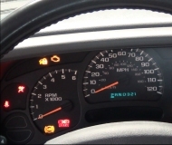
Motor hesitates and even stalls on acceleration

Tiny
TRAVIS MITTEN
  • MEMBER
  • 2001 MITSUBISHI MONTERO
  • 6 CYL
  • 4WD
  • AUTOMATIC
  • 85,000 MILES
Mitsubishi
Montero 4WD 3.5L
2001

Hi,
- runs well until taking a longer trip on hots days with stress on engine.
I am living out of the States now, and am having a hard time pinning down this problem. My Montero works fine around town and on short drives (responds well and idles well), but anything over twenty minutes or so (depending on how many mountains we climb) causes the motor to occasionally stall when I try to accelerate. More often, though, it will simply not respond at all when I press the gas. I would not even describe it as sputtering. It simply does nothing for a few seconds.

Here are a few other clues that seem significant: The problem appears to be related to outside temperature (when it rains, I have few to no problems, regardless of distance). Also, if I shut the motor off and and restart it, the problem goes away for five minutes or so (as though something is "reset").

I have replaced the fuel pump and recently installed an used Mass Air Flow Sensor, but the symptoms still occur. Other routine things, such as air filter and spark plugs, have all been well maintained. Because the problem only occurs on long trips (and because my Spanish is not great) it has been very difficult to have a mechanic diagnose it. Thanks for whatever advice you can give me.

Travis
Friday, May 27th, 2011 AT 10:06 PM

5 Replies

Tiny
KHLOW2008
  • MECHANIC
  • 41,814 POSTS
Is the Check Engine Light indicating and have you tried to retrieve for trouble codes?

Since the probem is temperature related, I would suggest checking the Engine Coolant Temperature.
Was this
answer
helpful?
Yes
No
Saturday, May 28th, 2011 AT 12:53 PM
Tiny
TRAVIS MITTEN
  • MEMBER
  • 5 POSTS
I have located a scanner and found several codes. Some (P0431)are probably due to the fact that the vehicle no longer has a catalytic converter (welcome to Central America!). Code P0125 did appear regarding insufficient coolant temp, but this seems to be the opposite of what I am experiencing (problem only occurs during hot weather and long drives).

Code P0110 (Intake air temp sensor) may be related. Is this a separate sensor or is it in the MAF sensor? I have already replaced the MAF with a used part and I had the same symptoms (I was hoping to diagnose the problem before getting a brand new part).

Codes P0170 and P0173 also show. Are these always related to fuel pump problems (because just replaced the fuel pump with a new part)?
Was this
answer
helpful?
Yes
No
Thursday, June 2nd, 2011 AT 5:58 PM
Tiny
KHLOW2008
  • MECHANIC
  • 41,814 POSTS
I would suggest clearing the codes, drive the vehicle around and see what codes comes back and go on from there.

P0431 Left warm up catalyst efficiency below threshold, bank 2. You are correct about it being due to a missing cat.

P0125: EXCESSIVE TIME TO ENTER CLOSED LOOP FUEL CONTROL

DTC Set Criteria
At least 30 seconds have passed since engine was started. Engine coolant temperature is more than 178°F (81°C). Engine speed is 1800-3500 RPM. Volumetric efficiency is 16-62 percent. Code will set when Multiport Fuel Injection (MFI) system does not enter closed loop control within 30 seconds of entering air/fuel feedback zone.

Probable Causes
†Heated Oxygen Sensor (HO2S) failed.
†Fuel injector failed.
†Fuel pressure regulator failed.
†Fuel pump failed.
†Fuel filter clogged.
†Intake system vacuum leak.
†Exhaust leak.
†Powertrain Control Module (PCM) failed.

DTC P0110: INTAKE AIR TEMPERATURE CIRCUIT MALFUNCTION
DTC Set Criteria
At least 2 seconds have passed since engine started. Code will set when IAT sensor output voltage has continued to be 4.6 volts or more, or 0.2 volt or less, for 2 seconds.

Probable Causes
†IAT sensor failed.
†Open or short in IAT sensor circuit, or loose connector.
†Powertrain Control Module (PCM) failed.

NOTE:
IAT sensor is located in Volume Airflow (VAF) sensor.

P0170 Right bank fuel trim malfunction ( Bank 1)

DTC P0170: RIGHT BANK FUEL TRIM MALFUNCTION (BANK 1)

DTC Set Criteria

†Engine is in closed loop air/fuel control. Engine coolant temperature is more than 14°F (-10°C). Intake air temperature is more than 14°F (-10°C). Barometric pressure is more than 11 psi (76 kPa). Volume Airflow (VAF) sensor output frequency is 100 Hz or more. Code will set if long-term fuel trim continues to be more than 12.5 percent, or less than -12.5 percent, and short-term fuel trim continues to be more than 7.4 percent, or less than -7.4 percent, for 10 seconds.

†Engine is in closed loop air/fuel control. Intake air temperature is more than 14°F (-10°C). Barometric pressure is more than 11 psi (76 kPa). VAF sensor output frequency is less than 100 Hz. Code will set if long-term fuel trim continues to be more than 12.5 percent, or less than -12.5 percent, and short-term fuel trim continues to be more than 12.4 percent, or less than -12.4 percent, for 5 seconds.

†Engine is in closed loop air/fuel control. Intake air temperature is more than 14°F (-10°C). Barometric pressure is more than 11 psi (76 kPa). VAF sensor output frequency is 100 Hz or more. Code will set if long-term fuel trim continues to be more than 12.4 percent, or less than -12.4 percent, and short-term fuel trim continues to be more than 7.4 percent, or less than -7.4 percent, for 5 seconds.

†Engine is in closed loop air/fuel control. Right front Heated Oxygen Sensor (HO2S) is active. Code will set if long-term fuel trim continues to be more than 12.5 percent, or less than -12.5 percent, and short-term fuel trim continues to be more than 25.5 percent, or less than -30.5 percent, for 5 seconds.

Probable Causes
†VAF sensor failed.
†Fuel injector No. 1, 3, or 5 failed.
†Incorrect fuel pressure.
†Air intake system leak.
†Right bank Heated Oxygen Sensor (HO2S) failed.
†Engine Coolant Temperature (ECT) sensor failed.
†Intake Air Temperature (IAT) sensor failed.
†Barometric Pressure (BARO) sensor failed.
†Exhaust system leak.
†Incorrect or contaminated fuel used.
†Powertrain Control Module (PCM) failed.

DTC P0173: LEFT BANK FUEL TRIM MALFUNCTION (BANK 2)
DTC Set Criteria

†Engine is in closed loop air/fuel control. Engine coolant temperature is more than 14°F (-10°C). Intake air temperature is more than 14°F (-10°C). Barometric pressure is more than 11 psi (76 kPa). Volume Airflow (VAF) sensor output frequency is 100 Hz or more. Code will set if long-term fuel trim continues to be more than 12.5 percent, or less than -12.5 percent, and short-term fuel trim continues to be more than 7.4 percent, or less than -7.4 percent, for 10 seconds.

†Engine is in closed loop air/fuel control. Intake air temperature is more than 14°F (-10°C). Barometric pressure is more than 11 psi (76 kPa). VAF sensor output frequency is less than 100 Hz. Code will set if long-term fuel trim continues to be more than 12.5 percent, or less than -12.5 percent, and short-term fuel trim continues to be more than 12.4 percent, or less than -12.4 percent, for 5 seconds.

†Engine is in closed loop air/fuel control. Intake air temperature is more than 14°F (-10°C). Barometric pressure is more than 11 psi (76 kPa). VAF sensor output frequency is 100 Hz or more. Code will set if long-term fuel trim continues to be more than 12.4 percent, or less than -12.4 percent, and short-term fuel trim continues to be more than 7.4 percent, or less than -7.4 percent, for 5 seconds.

†Engine is in closed loop air/fuel control. Left front Heated Oxygen Sensor (HO2S) is active. Code will set if long-term fuel trim continues to be more than 12.5 percent, or less than -12.5 percent, and short-term fuel trim continues to be more than 25.5 percent, or less than -30.5 percent, for 5 seconds.

Probable Causes

†VAF sensor failed.
†Fuel injector No. 2, 4, or 6 failed.
†Incorrect fuel pressure.
†Air intake system leak.
†Left bank Heated Oxygen Sensor (HO2S) failed.
†Engine Coolant Temperature (ECT) sensor failed.
†Intake Air Temperature (IAT) sensor failed.
†Barometric Pressure (BARO) sensor failed.
†Exhaust system leak.
†Incorrect or contaminated fuel used.
†Powertrain Control Module (PCM) failed.
Was this
answer
helpful?
Yes
No
Thursday, June 2nd, 2011 AT 6:27 PM
Tiny
TRAVIS MITTEN
  • MEMBER
  • 5 POSTS
I used a scanner on a long trip and found that the code which occurred at the moment I was experiencing problems was code P0170. I had already had the fuel pump changed, and had already tested another used VAF (MAF) sensor. I am now having the oxygen sensors changed (the two nearest the motor). What else should I be thinking about?
Was this
answer
helpful?
Yes
No
Wednesday, June 15th, 2011 AT 3:08 PM
Tiny
KHLOW2008
  • MECHANIC
  • 41,814 POSTS
Here are the Diagnostic Procedure for P0170.

1. Check exhaust system for leaks. If problem exists, repair exhaust leak as necessary, then go to step 16. If problem does not exist, go to next step.

2. Check intake system for vacuum leaks. If problem exists, repair vacuum leak as necessary, then go to step 16. If problem does not exist, go to next step.

3. Start engine and warm up to normal operating temperature. Using scan tool, check data list item No. 12 (volume airflow). At idle, VAF reading should be 17-46 Hz. At 2500 RPM, VAF reading should be 63-103 Hz. If VAF reading is within specifications, go to next step. If reading is not within specifications, check VAF sensor circuit.

4. Using scan tool, check data list item No. 13 (intake air temperature). Intake air temperature, as measured with a thermometer, and temperature displayed on scan tool should be within 10 percent of each other. If temperature is as specified, go to next step. If temperature is not as specified, check air temperature circuit.

5. Using scan tool, check data list item No. 21 (engine coolant temperature). Engine coolant temperature and temperature displayed on scan tool should be within 10 percent of each other. If temperature is as specified, go to next step. If temperature is not as specified, check engine coolant temperature circuit.

6. Using scan tool, check data list item No. 25 (barometric pressure). Compare reading with expected value. If scan tool reading is as specified, go to next step. If scan tool reading is not as specified, check barometric pressure circuit.

7. Measure resistance of following fuel injector circuits:

For fuel injector No. 1, measure between fuel injector intermediate
connector B-44 terminals No. 3 and 8 (component side).

For fuel injector No. 3, measure between fuel injector intermediate
connector B-44 terminals No. 1 and 8 (component side).

For fuel injector No. 5, measure between fuel injector intermediate connector B-44 terminals No. 6 and 8 (component side).

Each resistance should be 13-16 ohms at 68°F (20°C). If resistances are as specified, go to step 10. If any resistance is not as
specified, go to next step.

8. Remove intake manifold. Disconnect connector to fuel injector that failed resistance test in previous step. Measure resistance between fuel injector connector terminals (component side). Resistance should be 13-16 ohms at 68°F (20°C). If resistance is as not specified, replace fuel injector, then go to step 16. If resistance is as specified, go to next step.

9. Check connector to fuel injector that failed step 7). If problem exists, repair connector, then go to step 16. If problem does not exist, repair appropriate wire between fuel injector connector and fuel injector intermediate connector B-44, then go to step 16.

10. Check fuel injector intermediate connector B-44 for loose, damaged, or corroded terminals. If problem exists, repair connector, then go to step 16. If problem does not exist, go to next step.

11. Check PCM 35-pin connector D-107 for loose, damaged, or corroded terminals. If problem exists, repair connector, then go to step 16. If problem does not exist, go to next step.

12. Check for damage to following wires:

Check Yellow/Blue wire between fuel injector No. 1 connector terminal
No. 2 and PCM connector D-107 terminal No. 1.

Check Light Green wire between fuel injector No. 3 connector terminal No. 2 and PCM connector D-107 terminal No. 24.

Check Blue wire between fuel injector No. 5 connector terminal No. 2 and PCM connector D-107 terminal No. 10.

If problem exists, repair appropriate wire, then go to step 16. If problem does not exist, go to next step.

13. Check fuel pressure. At idle, fuel pressure should be 39 psi (270 kPa) with fuel pressure regulator vacuum line connected and 47-50 psi (330-350 kPa) with fuel pressure regulator vacuum line disconnected. If fuel pressure is as specified, go to next step. If fuel pressure is
not as specified, repair as necessary, then go to step 16.

14. Check for fuel contamination. If problem exists, replace fuel, then go to step 16. If fuel is okay, go to next step.

15. Replace right bank fuel injectors. Test drive vehicle following OBD-II drive cycle fuel trim monitor pattern. Check for DTCs. If DTC
P0170 is output, replace PCM, then go to next step. If DTC P0170 is not output, inspection is complete.

16. Test drive vehicle following OBD-II drive cycle fuel trim monitor pattern. Check for DTCs. If DTC P0170 is output, retry diagnostic procedure. If DTC P0170 is not output, inspection is complete.
Was this
answer
helpful?
Yes
No
Wednesday, June 15th, 2011 AT 4:32 PM

Please login or register to post a reply.

Sponsored links