2001 dodge grand caravan wiring problem

2001 DODGE CARAVAN
12,300 MILES • 6 CYL • FWD • AUTOMATIC
Avatar
LARRYSAMMONS
  • MEMBER
  • 24 POSTS
i have a 2001 dodge grand caravan 3.3L it has a pulse to the injectors and a signal to the coilpacks but no hot to either one. does anyone have a wiring diagram for the engine. can anyone help me thank you.

May 4, 2011 at 4:06 AM
Advertisement
Avatar
CARADIODOC
  • CERTIFIED EXPERT
  • 34,308 POSTS
How did you find pulses to the coils and injectors? The same sensors that time those pulses turn on the automatic shutdown relay that sends voltage to those items. My guess is you're finding those pulses while cranking the engine but checking the voltage while not cranking. Does that sound right?

The Engine Computer turns on the automatic shutdown (ASD) relay for one second after you turn on the ignition switch, then it turns it back off. You might hear the fuel pump run for that one second. There will also be battery voltage on the dark green / orange wire at the coils, injectors, and small wires on the back of the alternator. That voltage will only return when pulses are received from the crankshaft position sensor and camshaft position sensor. That means you must test for that voltage during engine cranking.

If that voltage is missing during cranking, suspect those two sensors. There will usually be a diagnostic fault code stored in the Engine Computer so it is important to not disconnect the battery or that valuable information will be lost. Reading those codes is the best place to start. They will lead you to the circuit or system with the problem, not necessarily the defective part.

If you DO find voltage on the dark green / orange wire during cranking, is is much more likely the fuel pump isn't starting up. You can prove that by testing the fuel pressure. If the pump is dead, it will often start up if you bang on the bottom of the fuel tank while a helper cranks the engine.
May 4, 2011 at 4:31 AM
Avatar
LARRYSAMMONS
  • MEMBER
  • 24 POSTS
were does the power go after the shut off relay [asd] it comes on but there is still no power not even for the one sec. and there is a pulse when u crank and the fuel pump never runs the codes are 0118,0123,0509 thanks
May 4, 2011 at 3:11 PM
Advertisement
Avatar
CARADIODOC
  • CERTIFIED EXPERT
  • 34,308 POSTS
Okay, just when I had everything memorized, they changed things, . . . again! The closest service manual I have is a 2002 which shows different wire colors than the older models. I sent you looking for a dark green / orange wire but instead you might have a brown / white wire feeding the injectors and coil pack.

The fuel pump has its own relay so it would appear both the ASD and pump relays are not turning on or the common power feed is missing. For starters, measure the voltage on fuses 16 (25 amp) and 17 (20 amp). That voltage comes right off the battery.

If it's there, remove the ASD or pump relay and check for voltage on terminal 87. If you have it there, use a piece of wire or stretched out paper clip to jump terminals 30 and 87 together in the socket. The pump should run or you should have voltage at the coil pack and injectors. If you do, that means those relays aren't being turned on by the Engine Computer. You might be able to feel them click but I prefer to pop the cover off a relay, reinstall it that way, then watch the contact when a helper turns on the ignition switch.

Holler back with the results of your testing. In particular, do those relays turn on at all? If they do not, check for voltage on terminal 86 in the relay socket when the ignition switch is in the "run" position. For a more accurate test, it is best to leave at least one of the relays installed so there is a load on the circuit.
May 4, 2011 at 4:31 PM
Avatar
CARADIODOC
  • CERTIFIED EXPERT
  • 34,308 POSTS
Woops; sorry, I overlooked your comment that the relays turn on. Check for voltage on those two fuses.
May 4, 2011 at 4:33 PM
Avatar
LARRYSAMMONS
  • MEMBER
  • 24 POSTS
im sorry the relay does not come on. lets start over. i checked every thing you said the fuses have 11.5 volts.someone had worked on it before me so its a mess. to start with the van run fine thay went out the next morning and it would not start. ok now as i said i checked the fuses thay had 11.5 v i was looking and there was a relay missing a ASD relay i put one in it now it has 11.4 volts to the coil,injectors and alt. only when cranking, and no injector pulse,or signal to the coil.the shut off relay and fuel pump realy has 11.4 volts but nether of them are working when key is on or cranking. i did like you said and crossed out the fuelpump relay and the fuel pump came on.so any ideas thank you for your help
May 4, 2011 at 9:28 PM
Avatar
LARRYSAMMONS
  • MEMBER
  • 24 POSTS
one more thing the check engine light comes one then blinks 9 time then stays on. the guy that owns it said sometimes the door would lock and unlock and the headlights would come on and go off on there own. i dont no if any of this means anything. thanks again
May 4, 2011 at 9:48 PM
Avatar
CARADIODOC
  • CERTIFIED EXPERT
  • 34,308 POSTS
Clarify this:

"there was a relay missing a ASD relay i put one in it now it has 11.4 volts to the coil,injectors and alt. only when cranking"

"but nether of them are working when key is on or cranking"

The way I'm reading this, you're saying two different things. If those relays are not turning on during cranking, the first suspect is the crankshaft position sensor or the camshaft position sensor. One thing that might help is checking for diagnostic fault codes which can point to the circuit with the problem. Chrysler makes that very easy. Do you know how to read them by cycling the ignition switch three times within five seconds? The codes should read out in the odometer display. There should be at least one related to the missing ASD relay. Hopefully there will be more.

It's the pulses from those two sensors that tell the computer to turn on the ASD relay. On newer models that will occur and the engine will still run if the cam sensor fails but the crank sensor has to work. On older models both sensors have to work for the relay to turn on. I'm not sure where a 2001 falls in there.

Be aware too that if you remove the crank sensor, it requires a paper spacer to be stuck to the end of it when reinstalling it to set the air gap. If you just shove it in all the way and pull it back a little, you'll have no idea what the gap is. I got stung by doing that once. If you stuff it in all the way without a spacer, it can hit the ring on the flex plate and break.
May 4, 2011 at 10:17 PM
Avatar
LARRYSAMMONS
  • MEMBER
  • 24 POSTS
i put a asd relay in it and when u crank the engine the relay is working and when u stop cranking it the relay kicks off. i ment the fuel pump and shut off relay are not working at all. the fuel pump relay dont even work for that 1 or 2 sec. when u first turn the key on.the cods arep0123,p0118,p1598,p1282,p1193,p0509,
May 5, 2011 at 1:23 AM
Avatar
CARADIODOC
  • CERTIFIED EXPERT
  • 34,308 POSTS
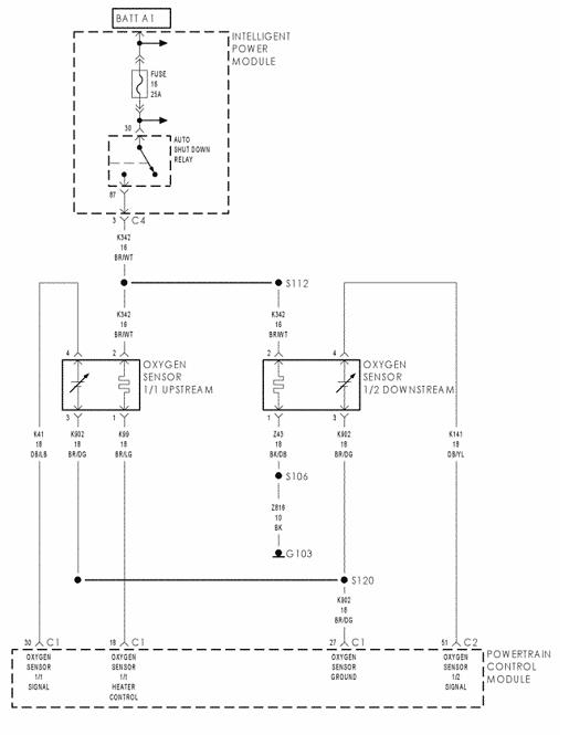
In your first sentence the automatic shutdown relay is working properly. In your second sentence you said both are not working at all. Last, you said the fuel pump relay is never turning on. That can't be good! and that's where we should start.

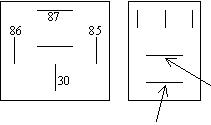
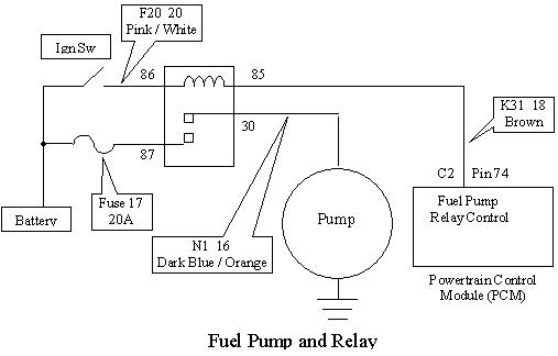
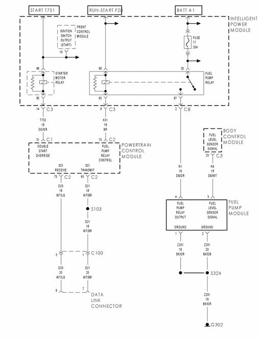
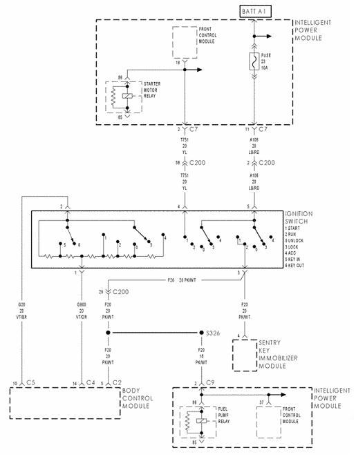
Grab a test light, (or a digital voltmeter), remove the fuel pump relay, and test for voltage on terminal 86. The voltage comes right off the ignition switch so that will have to be in the "run" position.

Next, move the ground clip for the test light to the battery positive post and probe terminal 85. We're testing for a ground circuit now. The light should light up for one second when you turn the ignition switch on and again during cranking.

One of those two circuits has to be not working. In fact, your code 1282 is for "Fuel Pump Relay Control Circuit". That's terminal 85 but the code doesn't specify if it detected that due to missing supply voltage on terminal 86 or if there is no current flow through the circuitry in the computer. In other words, did it set the code for a problem within the computer itself, a problem in the rest of the van's circuitry, or did it set simply from you pulling the relay out while the ignition switch was on? I don't know if removing the relay will set that code right away or if other conditions must also be present.

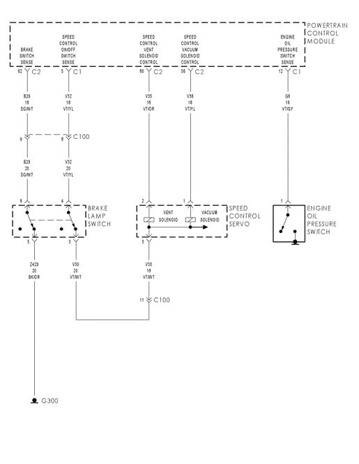
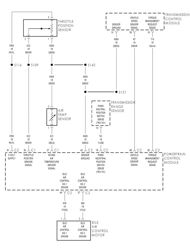
Now, here's something else that might be related. Code 123 is for the throttle position sensor signal voltage too high. 118 is for coolant temperature sensor voltage too high, and 1598 is for the air conditioning pressure sensor voltage too high. The only way any of those sensors can read too high is if there is a physical break inside it or the ground wire has a break. Now, here's where it gets interesting, and confusing. All three of those sensors share a common ground wire, so it's extremely likely that wire is open. It is very rare to have an open sensor, and it's REALLY REALLY unlikely three of them are open at the same time, unless those codes were set because they were unplugged while the ignition switch was on. That might be all that happened because there are many other sensors that also share that common ground wire and they didn't set codes. If you unplugged those three sensors, you can disregard this entire paragraph. If you didn't unplug 'em, check for voltage on dark blue / dark green wire on the throttle position sensor. That should be the easiest one to access. Normal voltage is 0.2 volts. If you find 5.0 volts, (ignition switch on), there is a break in that circuit that we have to narrow down.

To add to this, if that wire really is broken, there is a specific set of conditions that must be met for a fault code to set and one of them is that certain other codes are not already in memory. That is because the computer often compares one to another and if it knows it can't believe or trust one sensor's reading, it can't compare other sensors to it.

See where these tests take you, then holler back with what you find.
May 5, 2011 at 3:11 AM
Avatar
LARRYSAMMONS
  • MEMBER
  • 24 POSTS
87 is the only one with 12v 86 has nothing on it with key on or off. 85 is weard with the key off when i put the clip on the hot side and i stuck the tester in it the realays clicked and the dash lights were on and the test light was on when i turned the key in the test light went off when i cranked the engine the test light still didnt come on. and the dark blue/ dark green wire had 0.2v thank you for helping me.
May 5, 2011 at 5:06 PM
Avatar
CARADIODOC
  • CERTIFIED EXPERT
  • 34,308 POSTS
Dandy. We're making progress. 87 is the 12 volt supply to the relay contact. He's good. 86 needs 12 volts from the ignition switch. He's missing and must be checked further. As for 85, the ground circuit you're testing is switched on and off inside the Engine Computer. The test light just takes the place of the relay's coil, but the clip on the battery positive post is taking the place of the missing 12 volts from the ignition switch. That is probably feeding through the computer circuitry to the circuits for some of the other relays. That probably is not a very informative test, especially since we already know terminal 86 is dead.

I think you're going to find a defective ignition switch. You can double-check that you have voltage on the feed fuse # 23, but that one also feeds the starter relay through a different set of contacts in the switch. Since it cranks, that circuit must be good. You can verify that at the switch connector after you remove the trim covers under the steering wheel. 12 volts comes in on the 20 gauge light blue / red wire and goes out on the 20 gauge pink / white wire when the switch is in the "run" or "crank" position. If you have it on the first one but not on the second one, first check the connector for signs of melting and overheated terminals. That would seem strange. Overheated terminals are rather common but not on that circuit because it's a relatively low current circuit. That happens more often to a different circuit that feeds the power windows, radio, and heater fan and it acts up more for people who use the heater fan on the highest setting often. Regardless, if the switch is the problem, use a piece of wire to jump the light blue / red wire to the pink / white wire, then try to start it. Oh, don't forget to stick the relays back in first.

If you DO find 12 volts on the pink / white wire when the ignition switch is in the "run" position, there has to be a break in that wire between the switch and fuse box. We'll continue narrowing it down if it comes to that.
May 5, 2011 at 8:23 PM
Avatar
LARRYSAMMONS
  • MEMBER
  • 24 POSTS
i did what you said and there is still no hot 12v at term 86.
May 6, 2011 at 4:44 AM
Avatar
CARADIODOC
  • CERTIFIED EXPERT
  • 34,308 POSTS
What voltages did you find on the two wires at the ignition switch?
May 6, 2011 at 6:03 AM
Avatar
LARRYSAMMONS
  • MEMBER
  • 24 POSTS
light blue/red 12.30v pink/white 12.15v pluged up and key on.
May 6, 2011 at 1:31 PM
Avatar
CARADIODOC
  • CERTIFIED EXPERT
  • 34,308 POSTS
Okay, you gots 12.15 volts on the pink / white at the ignition switch but 0 volts at terminal 86 in the relay socket. Unless your '01 is different than the diagram in my '02 book, all that's in between those two points is that wire. Double check for voltage at terminal 86 with the ignition switch on. If it's really missing, there has to be a break in that wire.

Check for voltage on terminal 85 just for fun. There was a mistake in one of my service manuals a few months ago and they showed 85 and 86 switched around.
May 6, 2011 at 2:50 PM
Avatar
LARRYSAMMONS
  • MEMBER
  • 24 POSTS
85 has 12.13v with key on only
May 6, 2011 at 7:07 PM
Avatar
LARRYSAMMONS
  • MEMBER
  • 24 POSTS
87 is hot all the time. 86 is ground all the time. 85 is hot with the key on only. 30 has nothing on it.
May 7, 2011 at 12:24 AM
Avatar
CARADIODOC
  • CERTIFIED EXPERT
  • 34,308 POSTS
Okay, 85 and 86 are backwards according to my book. Well, wait a minute. How are you determining 86 is ground? Describe your test procedure.

You might want recheck for voltage on 85 with the fuel pump relay AND the ASD relay removed. Even though the ground circuits are on different pins in the computer connector, one might be back-feeding to the other relay socket.

If you still find voltage on 85, reinstall all the relays and add a piece of wire to the ASD relay terminal 86 so you can access it with the relays in place. Now, after the ignition switch has been on for more than a second, you should find 12 volts on 86. That voltage is coming from 85 and through the relay's coil. During cranking, the computer is supposed to ground that terminal to turn on the relay so you should see 0 volts then.

Just so we don't burn something up in the next step, use another piece of wire in terminal 85 so you can check the voltage there too.

I think before I go on, holler back with the answers to my questions so I can be more confident in the terminal numbers I'm using.
May 7, 2011 at 1:30 AM
Avatar
LARRYSAMMONS
  • MEMBER
  • 24 POSTS
with key off the ASD has hot on pin 87 on 85 30 and 86 thay have nothing it is the same with key on. now the fuel pump with key off you have hot on 87 on85 and 30 you have nothing on 86 you have a week ground but that is because that pin goes to the fuel pump. with key on you have a hot on 87 and 85 on 30 you have nothing not even for that 1 second when you first turn the key on.85 has that week ground but we no what that is i have a lot of wire cut under the hood and under dash can u please put a copy of the under hood and under dash wiring diagram on this page so i came print them off thank you
May 9, 2011 at 4:08 PM
Avatar
CARADIODOC
  • CERTIFIED EXPERT
  • 34,308 POSTS
Sorry for the delay. High winds, trees down, power out, 'puter dead until a few minutes ago.

You gotta put some commas in the sentences. Are you saying you find no voltage to 85 AND 86 with the ignition switch on? If so, you have to have a broken wire between the switch and relay. That's the pink / white wire.

I would love to post diagrams for you but I have never been able to get into the web sites we have access to. The best I can do quickly is to describe the circuits and wire colors. If you need more than that, I can make some line drawings in MS Word, then convert them to JPEGS that I can post here.
May 10, 2011 at 4:59 AM
Avatar
LARRYSAMMONS
  • MEMBER
  • 24 POSTS
With key off the ASD has hot on pin 87.On 85 30 and 86 thay have nothing. It is the same with key on. Now the fuel pump with key off you have hot on 87. 85 and 30 you have nothing.On 86 you have a week ground but that is because that pin goes to the fuel pump. With key on you have a hot on 87 and 85.On 30 you have nothing not even for that 1 second when you first turn the key on.85 has that week ground but we no what that is. I have a lot of wire cut under the hood and under dash.can u please put a copy of the under hood and under dash wiring diagram on this page so i came print them off thank you. Sorry and any wiring diagrams you can send will help
May 10, 2011 at 3:17 PM
Avatar
CARADIODOC
  • CERTIFIED EXPERT
  • 34,308 POSTS
My manual shows 87 and 86 tied together so they both should have voltage at the same time. I've heard stories about loose or corroded rivets on the brass strips connecting the terminals under the fuse box but I've never run into that myself.

I'm not sure what you mean by a "weak ground" for the fuel pump relay. 86 doesn't go to the fuel pump. 30 is the relay contact that goes to the pump. That one should read continuity to ground. If you measure it with an ohmmeter, you can expect a reading of about one or two ohms.

I'm working on drawing some diagrams for you. I find it much easier figuring out how a circuit works from looking at them vs. reading a written description. I'll post it as soon as I have something of value drawn up.
May 10, 2011 at 8:59 PM
Avatar
CARADIODOC
  • CERTIFIED EXPERT
  • 34,308 POSTS
See how far these get you.
May 11, 2011 at 12:00 AM
Avatar
LARRYSAMMONS
  • MEMBER
  • 24 POSTS
see what u can do on the diagrams. i can run a hot wire to 85 and the fuel pump comes on . could these diagrams be rong and 30 and 85 be backwards. see what u can find out. and thank for all your help.
May 11, 2011 at 3:10 AM
Avatar
CARADIODOC
  • CERTIFIED EXPERT
  • 34,308 POSTS
If you're running that hot wire to the socket without the relay installed, that has to be terminal 30. It is the lower part of the two terminals that form the letter "T".

To add to the misery, I have an '01 here right now and just went out and checked, and my drawing up higher is wrong again so I'll be changing it for the third time. Terminals 85 and 86 are reversed. Here's the drawing again with the numbers corrected. If you want to double-check, the numbers are molded on the bottom of the relays.

Okay, NOW tell me which one you're applying 12 volts to. 12 volts to terminal 30 should make the pump run without the relay installed. 12 volts to terminal 86 with the relay installed will not activate it only because 85 also has to be grounded for the relay to turn on, and it gets grounded by the circuitry inside the Engine Computer. Now that the drawing is corrected, (sorry), see if 12 volts appears on terminal 86 when the ignition switch is turned on.
May 11, 2011 at 5:40 AM
Avatar
LARRYSAMMONS
  • MEMBER
  • 24 POSTS
i will check that . but if u put a picture of a diagram on this page its not on here. if so can u try and put it on here again. sorry for the trouble. i called the guy that owns the van and the guy that worked on it before me changed the fuse box. could thay have put the wrong one in it. or are thay all the same.
May 11, 2011 at 9:56 PM
Avatar
CARADIODOC
  • CERTIFIED EXPERT
  • 34,308 POSTS
Some vehicles, (Dakotas, for one), use one fuse box, then they plug in different "joint connectors" to match the engine size and set of optional equipment on the vehicle. I don't see those joint connectors on the van I have here.

I double-checked the relay terminals. This is getting frustrating. Now that I corrected 85 and 86, 30 and 87 are also turned around. My drawings are correct for a 2002 model. I just checked the 2001 van that I have here and the 12 volt feed is terminal 30 for both relays. That means if you remove the pump relay, and jump 12 volts to 87, the pump should run. I was going to post a corrected diagram, . . . again, but I don't have a 2001 service manual so I can't tell if it will have the same wire colors. Instead, in the previous two drawings, switch 30 and 87 for both relays. 30 are the ones connected to the battery / fuse.
May 12, 2011 at 2:00 AM
Avatar
LARRYSAMMONS
  • MEMBER
  • 24 POSTS
i got the write fuse box. every thing is ok now but still wont stary no spark to plugs on pulse to fuel injectors non what .i can run o fake ground to fuel pump relay and it comes on. i need a wiring diagram to the computer do u have one? thanks the cam sensor is working fine. but the crank sensor its like it dont work at all.
May 23, 2011 at 7:33 PM
Avatar
CARADIODOC
  • CERTIFIED EXPERT
  • 34,308 POSTS
I can't post diagrams and I'm on a backup computer. The site stopped working on my main computer.

If the crankshaft position sensor isn't working, the ASD relay will not be turned on. The Engine Computer must see pulses from the cam and crank sensors before it will turn the ASD relay on, however, if the relay circuit is working, it WILL turn the ASD relay on for one second when you turn the ignition switch on.

I just finished six hours of copying diagrams from the Chrysler web site. Now I have to figure out how to convert them from MS Word files to jpegs that will post here. This was so easy on my main computer but that one uses Mozilla Firefox, and this site stopped working with Firefox last week. As soon as I can figure out how to convert them, I should have some diagrams for you. Yippee! Internet Explorer is so miserable to use after getting used to Firefox.
May 24, 2011 at 8:54 AM
Avatar
LARRYSAMMONS
  • MEMBER
  • 24 POSTS
i can wait sorry your computer missed up. but i would reale be thankfull if u can post the computer wiring diagram . i think there is a wire broke going to the crank sensor but i dont no witch wire to check thank u for all your help
May 24, 2011 at 2:17 PM
Avatar
CARADIODOC
  • CERTIFIED EXPERT
  • 34,308 POSTS
Okay, see how far you get with these. This is every diagram related to "Fuel / Ignition" and one for "Power Distribution".
May 25, 2011 at 6:01 AM