Hi,
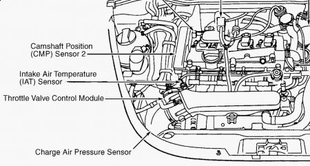
The engine's idle speed is controlled by the throttle body control module. In this case, we need to first make sure the throttle body is clean. Take a look through this link it explains how to service one:
https://www.2carpros.com/articles/throttle-actuator-service
If that is clean, then we need to check the throttle valve control module. Here are the directions for testing. This does require a scan tool to complete and is a bit complicated. However, if you have questions, let me know. All attached pics correlate with these tests.
__________________________
2000 Volkswagen New Beetle (1C1) L4-1.8L Turbo (APH)
With Generic Scan Tool
Vehicle Powertrain Management Relays and Modules - Powertrain Management Relays and Modules - Computers and Control Systems Electronic Throttle Control Module Testing and Inspection Component Tests and General Diagnostics Throttle Valve Control Module J338, Checking With Generic Scan Tool
WITH GENERIC SCAN TOOL
Throttle Valve Control Module, Checking
NOTE: Use only gold-plated terminals when servicing terminals in harness connector of throttle valve control module.
Function
The throttle valve activation occurs via an electric motor (throttle drive) in the throttle valve control module. It is activated by the Engine Control Module (ECM) according to specifications of the two sensors, Throttle Position (TP) Sensor -G79- and Sender -2- for accelerator pedal position -G185-, function of the E-gas system.
Components of Throttle Valve Control Module -J338-:
- Throttle drive (power accelerator actuation) -G186-
- Angle sensor -1- for throttle drive (power accelerator actuation) -G187-
- Angle sensor -2- for throttle drive (power accelerator actuation) -G188-
Recommended special tools and equipment
- VAG1526 multimeter or VAG1715 multimeter
- VAG1594 connector test kit
- Wiring diagram
Test requirements
pic 1
- The respective fuses of Motronic Engine Control Module (ECM) -J220- must be OK.
- Battery voltage must be at least 11.5 volts.
- All electrical consumers such as, for example, lights and rear window defroster must be switched off.
- Parking brake must be engaged or else daylight driving lights will be switched on.
- If vehicle is equipped with an A/C system, it must be switched off.
- Ground (GND) connections between engine and chassis must be OK.
- Throttle valve must not be damaged or dirty.
- Coolant temperature must be at least 80 degrees C, Diagnostic mode 1: Check measuring values; PID 5, Coolant temperature.
Function test
- Connect diagnostic tester. See: Computers and Control Systems > Reading and Clearing Diagnostic Trouble Codes > Diagnostic Tester, Connecting
- Switch ignition on.
- Under address word 33, select "Diagnostic mode 1: Checking measured values."
- Select the measuring value "PID 17: Throttle valve position (absolute)."
- Check specified value of throttle valve position (absolute) at idle stop:
pic 2
- Slowly depress accelerator pedal up to Wide Open Throttle (WOT) stop while observing the percentage display.
The percentage display must increase uniformly.
- Check specified value of throttle valve position (absolute) at Wide Open Throttle (WOT) stop:
pic 3
- End diagnosis and switch ignition off.
If specified values are not obtained:
Check resistance
- Connect test box to control module wiring harness, connect test box for wiring test. Engine Control Module (ECM) is not connected.
- Measure resistance of throttle valve drive between test box sockets 117 +118
Specified value: 1...5 ohms
If specified value is not obtained:
- Replace Throttle Valve Control Module -J338-, item 20
- Erase DTC memory of Engine Control Module (ECM), Diagnostic mode 4: Reset/erase diagnostic data.
- Generate readiness code. See: Computers and Control Systems > Monitors, Trips, Drive Cycles and Readiness Codes
If specified value is obtained:
- Check voltage supply of throttle valve control module and wiring to control module.
- Check Throttle Position (TP) Sensor -G79- and Sender -2- for accelerator pedal position -G185-.
If voltage supply and wires are OK:
- Replace Motronic Engine Control Module (ECM) -J220-.
Checking voltage supply and wiring to control module
pic 4
- Disconnect 6-pin connector -2- at the throttle valve control module -1-.
pic 5
- Connect multimeter to terminals 2 + 6 of connector for voltage measurement.
- Switch ignition on.
Specified value: at least 4.5 V
- Switch ignition off.
pic 6
- Connect multimeter to terminal 2 of connector and Ground (GND) for voltage measurement.
- Switch ignition on.
Specified value: at least 4.5 V
- Switch ignition off.
- Connect test box to control module wiring harness, connect test box for wiring test.
Engine Control Module (ECM) is not connected.
pic 7
- Check wires between test box and 6-pin connector for open circuit according to wiring diagram:
Terminal 1 + socket 92
Terminal 2 + socket 83
Terminal 3 + socket 117
Terminal 4 + socket 84
Terminal 5 + socket 118
Terminal 6 + socket 91
Wire resistance: max. 1.5 ohms
- Also check wires for short circuit to each other.
Specified value: Infinite Ohms
If no malfunctions are found in wires:
- Check voltage supply of Engine Control Module ECM). See: Engine Control Module > Component Tests and General Diagnostics > ECM Voltage Supply, Checking
- Erase DTC memory of Engine Control Module ECM), Diagnostic mode 4: Reset/erase diagnostic data.
- Generate readiness code. See: Computers and Control Systems > Monitors, Trips, Drive Cycles and Readiness Codes
_____________________________________________
Let me know what you find or if you have other questions.
Take care,
Joe
Images (Click to make bigger)
Monday, April 27th, 2020 AT 7:41 PM


