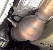
TEST HF: CATALYST EFFICIENCY MONITOR & EXHAUST SYSTEMS
NOTE: After each service or repair procedure has been completed, reconnect
all components. Clear DTCs and repeat QUICK TEST procedures to
ensure all EEC-V systems are working properly and DTCs are no longer
present.
Diagnostic Aids
Perform this test when instructed during QUICK TEST or if directed by other test procedures. This
test is used to diagnose the exhaust system and downstream HO2S.
Internal damage of a catalytic converter is usually caused by abnormal engine operation upstream of
catalyst. Conditions that produce higher than normal temperatures in the catalytic converter, such as
cylinder misfire, are likely suspects.
NOTE: If entering this test for symptoms only, go to step 5).
1) DTC P0420 Or P0430: Check Possible Cause Of Misfire
DTC P0420 indicates bank one catalyst system efficiency is below minimum requirement. DTC
P0430 indicates bank 2 catalyst system efficiency is below minimum requirement. Possible
causes are:
� Use of leaded fuel.
� Oil contamination.
� Cylinder misfire.
� Fuel pressure too high.
� HO2S sensor improperly connected.
� Damaged exhaust system component.
� Faulty ECT sensor.
� Faulty HO2S.
Retrieve all Continuous Memory DTCs. If misfire codes are not present, go to next step. See
MISFIRE DIAGNOSTIC TROUBLE CODES (DTC) table. If any misfire codes are present,
isolate cylinder and repair as necessary.
MISFIRE TROUBLE CODES
Misfire DTC Cylinder (PCM Pin No.)
P0301 No. 1 (75)
P0302 No. 2 (101)
P0303 No. 3 (74)
P0304 No. 4 (100)
P0305 No. 5 (73)
P0306 No. 6 (99)
ENGINE CONTROLS - SELF-DIAGNOSTICS - EEC-V -1999 Ford Contour SVT Page 1 of 3
10/8/2011
Misfire DTC Cylinder (PCM Pin No.)
P0307 No. 7 (72)
P0308 No. 8 (98)
P0309 No. 9 (68)
P0310 No. 10 (42)
P0300 (1)
(1) Multiple cylinder misfire or defective Crankshaft Position (CKP) sensor.
2) Check HO2S Monitor DTCs
If DTC P0136, P0138, P0141, P0156, P0158 or P0161 was present in step 1), perform
appropriate system test. See DIAGNOSTIC TROUBLE CODE (DTC) DEFINITIONS. If
none of these DTCs are present in step 1), go to next step.
3) Check For ECT Or CHT Sensor DTCs
If DTC P0117, P0118, P0125, P1117, P1285, P1288, P1289, P1290 or P1299 was present in
step 1), perform appropriate system test. If none of these DTCs are present in step 1), go to
next step.
4) Check For Other DTCs
If any other DTCs except P0420 and P0430 are present in step 1), perform appropriate system
test. If no other DTCs except P0420 and/or P0430 are present in step 1), go to next step.
5) Check Rear HO2S Wiring Harness
Turn ignition off. Ensure HO2S wiring harness is correctly routed and connectors are tight.
Repair as necessary. Disconnect PCM 104-pin connector. Inspect connector for loose, damaged
or corroded terminals. Also check PCM pins. If PCM pins are damaged, replace PCM. If wiring
harness and connectors are okay, go to next step.
6) Check Fuel Pressure
Turn ignition off. Release fuel pressure. See appropriate REMOVAL, OVERHAUL &
INSTALLATION article. On models equipped with a fuel pressure regulator on fuel rail, check
vacuum hose and vacuum supply to regulator. Repair as necessary. On all models, install fuel
pressure gauge. Start engine and allow to idle. Note fuel pressure gauge reading. Increase
engine speed to 2500 RPM and maintain for one minute. If fuel pressure is as specified, go to
next step. See FUEL PRESSURE SPECIFICATIONS. If fuel pressure is not as specified, go
to TEST HC.
7) Check For Exhaust System Leaks
If exhaust system leaks, it may cause catalyst monitor efficiency test to fail. Inspect exhaust
system for cracks, loose connections or punctures. Repair as necessary. If exhaust system is
okay, go to next step.
8) Check For Exhaust System Restrictions
ENGINE CONTROLS - SELF-DIAGNOSTICS - EEC-V -1999 Ford Contour SVT Page 2 of 3
10/8/2011
Inspect exhaust system for collapsed areas, dents or excessive bends. Repair or replace as
necessary. If exhaust system is okay, go to next step.
9) Check Manifold Vacuum
Install tachometer. Connect vacuum gauge to intake manifold vacuum source. Start engine and
raise engine speed to 2000 RPM. Manifold vacuum should increase to more than 16 in. Hg. If
manifold vacuum is okay, go to next step. If manifold vacuum is low, go to step 11.
10) Check Manifold Vacuum For Exhaust Restriction
Leave tachometer and vacuum gauge connected. Start engine and raise engine speed to 2000
RPM. On a non-restricted system, manifold vacuum increases quickly to normal range as
increased RPM is maintained. On a restricted system, manifold vacuum increases slowly to
normal range as increased RPM is maintained. If manifold vacuum is okay, no indication of
exhaust leak or restriction has been detected and testing is complete. If manifold vacuum is low
or slow to respond, go to next step.
11) Check Manifold Vacuum
Leave tachometer and vacuum gauge connected. Disconnect exhaust pipe from exhaust
manifold. Start engine and raise engine speed to 2000 RPM. If manifold vacuum is now okay,
fault is downstream from exhaust manifold. Reconnect exhaust pipe to exhaust manifold and go
to next step. If manifold vacuum is still low or slow to respond, restriction exists in exhaust
manifold. Repair as necessary.
12) Check Manifold Vacuum
Leave tachometer and vacuum gauge connected. Disconnect muffler/tailpipe assembly from
rear of catalytic converter. Start engine and raise engine speed to 2000 RPM. If manifold
vacuum is now okay, fault is in muffler/tailpipe assembly. Repair as necessary. If manifold
vacuum is still not okay, fault is in catalytic converter. Replace converter. After replacing
converter, check tailpipe/muffler assembly for debris from faulty catalytic converter.
ENGINE CONTROLS - SELF-DIAGNOSTICS - EEC-V -1999 Ford Contour SVT Page 3 of 3
Sunday, October 9th, 2011 AT 1:04 AM


