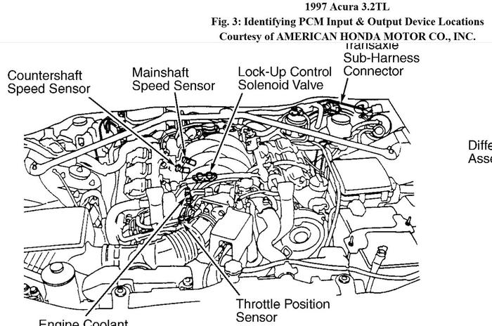
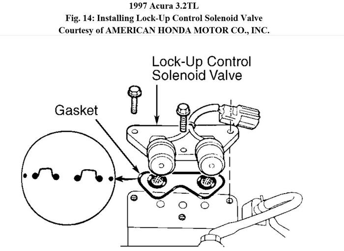
Here are the diagnostic procedures if it is of any help.
DTC P1753/FLASH CODE 1: LOCK-UP CONTROL SOLENOID "A"
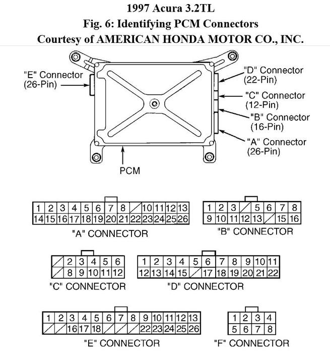
1. Turn ignition off. Disconnect PCM harness connectors "A" (26-pin) and "E" (26-pin). See Fig. 6. Turn ignition on. Check voltage between PCM harness connector "A" terminal No. 26 (Brown/Black wire) and harness connector "E" terminal No. 13 (Yellow wire). If voltage is present, go to next step. If voltage is not present, go to step 3.
2. Repair short to power in circuit between PCM harness connector "E" terminal No. 13 (Yellow wire) and lock-up control solenoid valve "A".
3. Turn ignition off. Check resistance between PCM harness connector "A" terminal No. 26 (Brown/Black wire) and harness connector "E" terminal No. 13 (Yellow wire). If resistance is not 12-25 ohms, go to next step. If resistance is 12-25 ohms, check for loose PCM connectors. Repair as necessary. If connectors are okay, substitute with a known-good solenoid valve assembly or PCM and recheck system. If symptom or problem goes away, replace faulty component.
4. Disconnect lock-up control solenoid valve harness connector. Check continuity between PCM harness connector "A" terminal No. 26 (Brown/Black wire) and harness connector "E" terminal No. 13 (Yellow wire). See Fig. 6. If continuity does not exist, go to next step. If continuity exists, repair short to ground in circuit between PCM harness connector terminal No. 13 (Yellow wire) and lock-up control solenoid valve
"A".
5. Check resistance between body ground and lock-up control solenoid connector
terminal No. 2 (Yellow wire). If resistance is not 12-25 ohms, replace lock-up control solenoid valve assembly. If resistance is 12-25 ohms, check for open in circuit between PCM harness connector "E" terminal No. 13 and lock-up control solenoid valve "A".
Image (Click to make bigger)
SPONSORED LINKS
Friday, November 2nd, 2012 AT 3:18 PM


