2005 Nissan Altima Intake Valve timing circuit

Tiny
WESTON07
  • MEMBER
  • 2005 NISSAN ALTIMA
  • 6 CYL
  • FWD
  • AUTOMATIC
  • 85,000 MILES
Hi there,

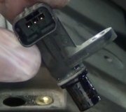
About 6 months ago my car starting making an awful ticking noise. I had to replace the tensioners for the timing chains on the camshafts. It was my first time ever doing a job like that. I replaced the water pump and all chain guides and tensioners so there would not be any future problems. When the job was finished my check engine light came on. The code it read was code P1111-"Intake Valve Timing Circuit Bank 1" I deleted the code thinking it might have triggered while I was working on the car. Well about a week later it came back on and will not turn off. I talked to a mechanic at Nissan and he said I needed to replace the "valve assembly solenoid valve timing control." Im not exactly sure what this is or where it is located. I am hoping it is not back inside of the timing chain cover! I would appreciate some good advice. Was also wondering if anyone knows where I can get a print out of the whole repair process. Thanks much

-Weston
Wednesday, September 15th, 2010 AT 3:01 PM

4 Replies

Tiny
ERNEST CLARK
  • MECHANIC
  • 1,730 POSTS
This mechanism hydraulically controls cam phases continuously with the fixed operating angle of the intake valve. Both sensors are located at the front of your engine (water pump side) at the junction between the valve covers and timing chain. Bank 1 will be on your left if you are facing the front of the motor.

Also, I suggest you purchase a single vehicle subscription to a data service such as alldata or mitchell 1. This will provide you with the necessary illustrations. Before removing these valves, test them thoroughly first.

Here's the procedure for testing.

TESTING:

1. Disconnect intake valve timing control solenoid valve harness connector.

2. Check resistance between intake valve timing control solenoid valve as follows. If NG, replace intake valve timing control solenoid valve.

If OK, go to next step.

3. Remove intake valve timing control solenoid valve.

4. Provide 12 V DC between intake valve timing control solenoid valve terminals and then interrupt it. Make sure that the plunger moves as shown in the figure.

CAUTION: Do not apply 12 V DC continuously for 5 seconds or more. Doing so may result in damage to the coil in intake valve timing control solenoid valve.
If NG, replace intake valve timing control solenoid valve.

NOTE: Always replace O-ring when intake valve timing control solenoid valve is removed.
Was this
answer
helpful?
Yes
No
Friday, September 17th, 2010 AT 9:39 AM
Tiny
WESTON07
  • MEMBER
  • 2 POSTS
Thank you very much! That was very helpful. I checked the solenoid and I believe it is ok. Is it possible that the Timing is out on Bank 1? That is the side that the tensioner was most worn out on. Could the reason for this code be the fact that the chain may have jumped a few teeth on the cams in Bank 1?
Was this
answer
helpful?
Yes
No
Friday, September 17th, 2010 AT 2:48 PM
Tiny
ERNEST CLARK
  • MECHANIC
  • 1,730 POSTS
It is possible that the computer sees (from the sensor) that your cam is not in correct faze. I really can't say for sure without testing it myself.

But a proper diagnosis is a process of elimination.
Was this
answer
helpful?
Yes
No
Saturday, September 18th, 2010 AT 5:16 AM
Tiny
DBIZZEL82
  • MEMBER
  • 1 POST
I know this is an old question but can you tell me how far the plunger should move should the passage ways be open all the way thanks in advance. Dustin
Was this
answer
helpful?
Yes
No
Wednesday, June 13th, 2012 AT 3:50 PM

Please login or register to post a reply.

Sponsored links